Navigation
Install the app
How to install the app on iOS
Follow along with the video below to see how to install our site as a web app on your home screen.
Note: This feature may not be available in some browsers.
More options
Style variation
-
Congratulations JStephen on being selected by the Eng-Tips community for having the most helpful posts in the forums last week. Way to Go!
You are using an out of date browser. It may not display this or other websites correctly.
You should upgrade or use an alternative browser.
You should upgrade or use an alternative browser.
Plate Deflection Calulation help
- Thread starter jazz330
- Start date
- Status
- Not open for further replies.
google "moody rectangular plates" ... that's the source for Roark and has more info in it.
the two important dim'ns are the width and the length of the plate (together with the thickness and the pressure).
another day in paradise, or is paradise one day closer ?
the two important dim'ns are the width and the length of the plate (together with the thickness and the pressure).
another day in paradise, or is paradise one day closer ?
What I'd really do is create a complete 3D model with proper loads and constraints, run FEA, and just use Roark/Moody to validate the results. Now that everyone and their mother has FEA built into their CAD system, it's so quick and easy it seems foolish not to use it for quick iteration of your virtual prototypes.
@IFRs, the OP's not hydroforming. My quick FEA spits out around .25" max deflection for a 18"x36" steel plate (roughly scaled from illustration). Unless the plate's in danger of buckling or yielding, that's definitely a small deflection. If you got a large deflection for a result, you'd know it warranted further investigation.
Plus, pencil and paper methods also make small-angle approximations.
Plus, pencil and paper methods also make small-angle approximations.
1/4" is greater than the material thickness by 25%. Is your FEA accurate for those deflections? Assuming it is, how does one not skilled in the art of FEA know what "small" deflections are and when the equations become less accurate? Maybe I'm just stuck in the past...
GregLocock
Automotive
...note that the Roark's equation does not account for membrane stiffness either!
Cheers
Greg Locock
New here? Try reading these, they might help FAQ731-376
Cheers
Greg Locock
New here? Try reading these, they might help FAQ731-376
No one above cared to ask how is the plate supported, possibly at the four corners?
Definitely solvable with formulae, but, jazz330, please first state some more data: supports, dimensions...
prex
[URL unfurl="true"]http://www.xcalcs.com[/url] : Online engineering calculations
[URL unfurl="true"]http://www.megamag.it[/url] : Magnetic brakes and launchers for fun rides
[URL unfurl="true"]http://www.levitans.com[/url] : Air bearing pads
GregLocock
Automotive
I jumped to the conclusion it was ss along the edges, but as you point out that is dangerous.
Cheers
Greg Locock
New here? Try reading these, they might help FAQ731-376
Cheers
Greg Locock
New here? Try reading these, they might help FAQ731-376
Hi jazz330,
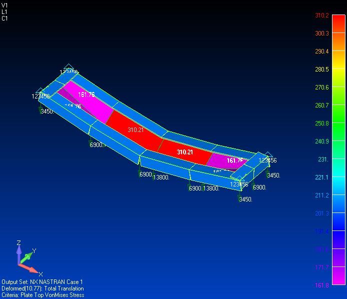
We need more information like measurements, I assumed that is 1x0.2m welded in 4 corners, you will have problems because the deflection is 10.77 mm and von mises stress is 310 MPa. (I assumed that material is A36 too).
P.D.: My english is very bad

We need more information like measurements, I assumed that is 1x0.2m welded in 4 corners, you will have problems because the deflection is 10.77 mm and von mises stress is 310 MPa. (I assumed that material is A36 too).
P.D.: My english is very bad

- Thread starter
- #15
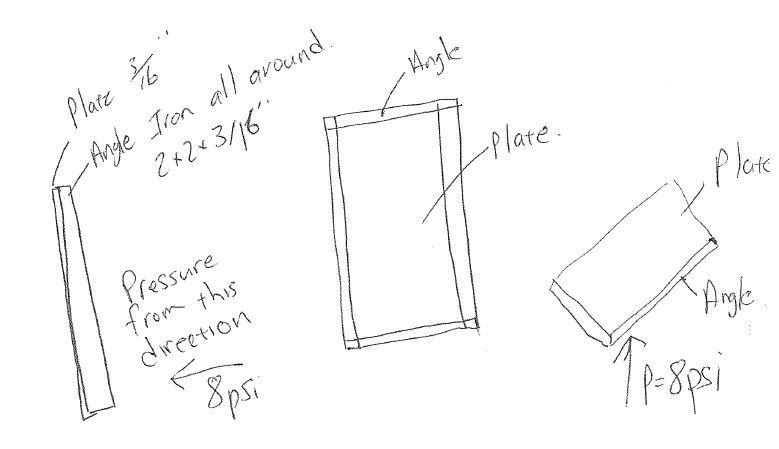
The plate is 3/16" Thick x 96" Wide x 240" High. The frame is made from 2"x2"x1/4" Angle Iron mitered and welded at the corners. The pressure is 8 psi coming from the side with the angle iron frame. All 4 sides are fixed not simply supported.
I have done hand calculations and FEA but I get a ridiculous value for Stress and deflection and I may be doing it wrong so any help would be great.
Thanks
I have done hand calculations and FEA but I get a ridiculous value for Stress and deflection and I may be doing it wrong so any help would be great.
Thanks
I don't see how a plate that big, with a so small thickness, could resist that pressure.
You should better describe the context and the goal of your analysis, as what you described is out of question.
Anyway your source is definitely the Roark, but also other sources online, google 'flat plates in bending' (example here, from the first site below).
If you insist with those dimensions and loading, you'll need to take into account the membrane action, and state whether the boundary is also fixed in the plane of the plate. Here a calc sheet for this condition.
prex
[URL unfurl="true"]http://www.xcalcs.com[/url] : Online engineering calculations
[URL unfurl="true"]http://www.megamag.it[/url] : Magnetic brakes and launchers for fun rides
[URL unfurl="true"]http://www.levitans.com[/url] : Air bearing pads
I think we're jumping the gun to say "your plate's no good ..."
Assume a deflection of 1", then the plate has formed to a radius of 1152" = (48^2+1)/2
Then hoop stress is 8*1152/0.1875 = 50ksi; so it is looking dodgy,but then maybe 1" dflection is on the small side, given the scale of this plate. a 2" deflection would about 1/2 the stress ... 1/48, about 2% ... not unreasonable.
stiffeners running across the plate (96" long) provide lots of bending strength to the plate, and reduce the stress in the plate.
But, don't count a simple angle to fix the edge, even if you support the standing leg all around the perimeter; the angle would easily "open up". A tube section around the perimeter would give you more fixity (plate bending is torque of the tube ...)
another day in paradise, or is paradise one day closer ?
- Status
- Not open for further replies.
Similar threads
- Replies
- 11
- Views
- 4K
- Replies
- 9
- Views
- 8K
- Question
- Replies
- 11
- Views
- 5K
- Replies
- 0
- Views
- 2K
- Replies
- 8
- Views
- 2K


