Eng-Tips is the largest engineering community on the Internet

Intelligent Work Forums for Engineering Professionals

Please confirm my drawing of a 240V to 120V wiring conversion

Status
Not open for further replies.

cavitate

Civil/Environmental
Aug 12, 2008
53
0
0
US
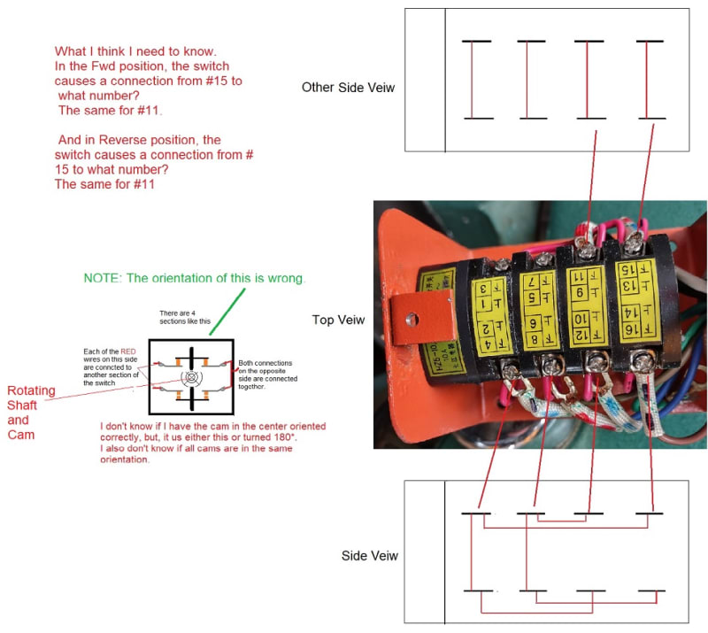
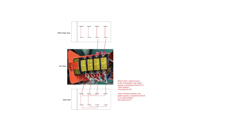
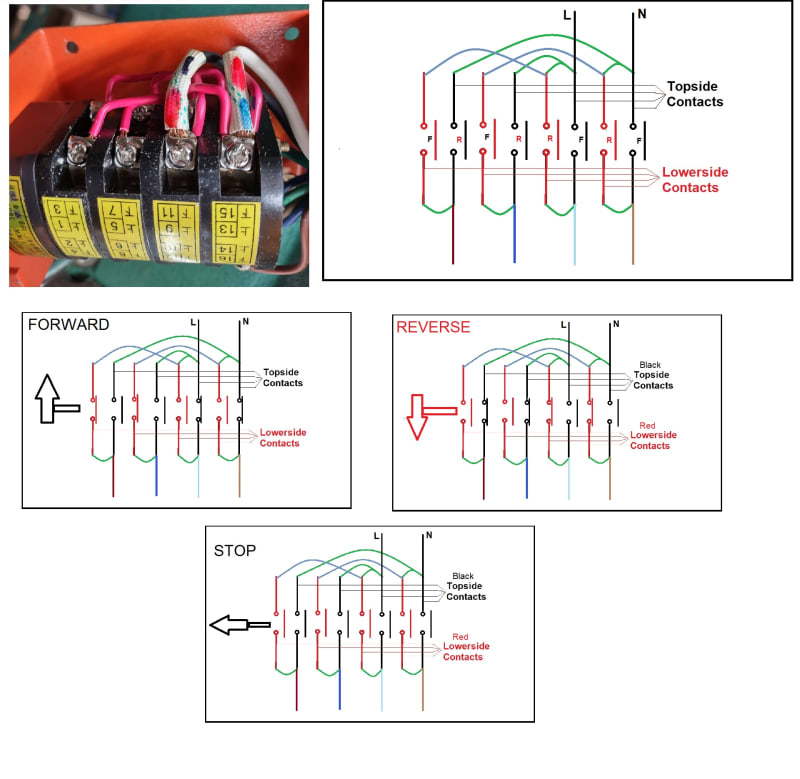
I'm trying to reassemble a 4 section double pole switch I disassembled.
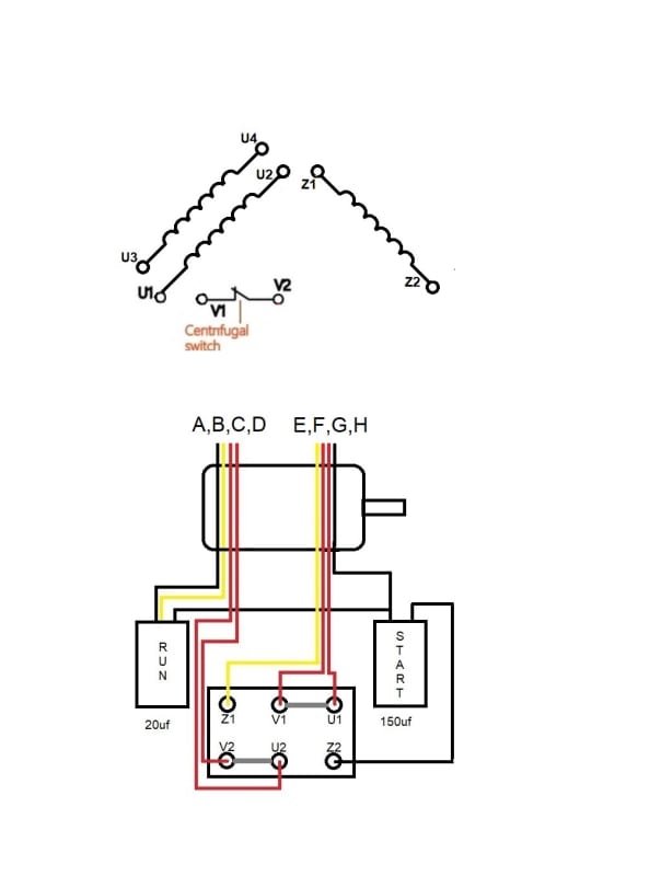
I need to backup and understand the internal wiring of the motor.
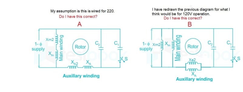
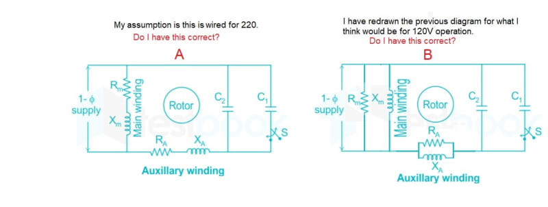
I found a diagram of a motor that I think is wired for 240V, and then I made a drawing
of what I think it would look like when changes to 120V operation.
Can anyone confirm I have it right so far?

Milling_machine_240V_or_120_wiring_isvs4x.jpg
 
Replies continue below

Recommended for you

No, you haven't got it right. What you have drawn is an equivalent circuit where R and X are the resistance and inductance of the same winding, they are not two windings like you have drawn (look at their different symbols).

Buy a 240/120 V transformer or a 110 V motor.

Muthu
 
Forget R[sub]A[/sub] and R[sub]M[/sub].
A typical 115/230 Volt motor will have three windings.
Two main 115 Volt windings that are in parallel for 120 Volts and in series for 240 Volt operation.
There will be one 115 Volt starting winding that is in parallel with one or the other of the main windings.
The starting capacitor is switched out of the circuit when the motor is almost up to speed.
The run capacitor (when present) will be in series with the start winding at all times.
The start and run capacitors are not interchangeable.
A starting duty capacitor will often fail if left in use continuously.
And then your motor may not be typical.
By the way, have you looked on the motor for a connection diagram?
The diagram may be on the back of the JB cover.
Or, buy a transformer.
Voltages:
220 Volts was phased out in the 50s.
110 Volts and multiples thereof were replaced by 112 Volts, then 115 Volts, 117 Volts and finally 120 Volts.
There was a jump in standard voltage every 5 years.
the conversion from the 110 Volt base to the 120 Volt base took 20 years.
Standard motor rated voltages are multiples of 115 Volts.
Standard system voltages are multiples of 120 Volts.
--------------------
Ohm's law
Not just a good idea;
It's the LAW!
 
>No, you haven't got it right. What you have drawn is an equivalent circuit where R and X are the resistance and inductance of the same winding, they >are not two windings like you have drawn (look at their different symbols).

OK, I thought it was odd that one winding was shown as a resistor. I'm well aware of resistance in an inductor, making and measuring high Q coils
is a bit of a hobby of mine. I'm not aware why the page I got the schematic from would show resistance of the motor winding, but it looks like they did. OK, my question still remains, the motor I have is changeable from 240 to 120, so let's assume that resistor symbol is a winding on the motor.
I have read that the start windings are sometimes not put in parallel as I have in a 240 to 120 conversion, but I don't know that is generally what happens.
I have redrawn the diagram with windings instead of resistors.
I have also added a second diagram. In that I want to know the internal motor diagram that will match the 8 wires I have going into the motor, and
how the 8 wires are connected. I made an attempt at the connections, but can't figure it out.
Mikek

Milling_machine_240V_or_120_wiring_edfx3t.jpg


milling_machine_motor_connections_to_UVZ_connector_block_internal_to_the_motor_uaszko.jpg
 
Waross said:
here will be one 115 Volt starting winding that is in parallel with one or the other of the main windings.
In a typical motor:
Main windings; 4 leads.
Start winding; 2 leads.
Start switch; 2 leads.
Your motor may not be typical.
Pictures?

--------------------
Ohm's law
Not just a good idea;
It's the LAW!
 
>There will be one 115 Volt starting winding that is in parallel with one or the other of the main windings.

That is one thing I don't understand, When running on 240 is the start winding still run on 120? i.e. 1 ph to ground? Or are there two start windings
put in series for 240V and parallel for 120V?

Yes on the voltage going up over time, not the issue.

>And then your motor may not be typical.
It is a Chinese, YL90-L4
I find several 3 section switch wiring diagrams, but no 4 section switch wiring diagrams.

I posted about the same time you posted, so I have to more diagrams for you to look at.
Here is the entire situation. I have Mill running on 120V. The switch quit working, I took it apart (mistake 1).
It is a 4 section, double pole, 3 position switch, I can wire it back as it was, but There are 4 cams and I don't
have the position of all for cams. So, I'm trying to work backwards from the motor, through the U1, U2, Z1, Z2, V1, V2
connection block to the switch to 120V. First problem I don't know what the motor looks like inside, i.e. connection, 3 winding or 4, etc.
I want to know that.
I'll add the motor plate to see if that adds any info. The one boxed in red is how the jumpers are.
Thanks, Mikek

Milling_Machine_Plate_diagram_ctbeul.jpg
 

>In a typical motor:
>Main windings; 4 leads.
>Start winding; 2 leads.
>Start switch; 2 leads.
>Your motor may not be typical.

4+2+2 is 8, that matches the number of wires I have going inside the motor.
So, now I would like to have is the internal diagram of the motor and how the 8 wires are connected inside the motor.
Thanks, Mikek

P.S. Still wondering, "When running on 240 is the start winding still run on 120? i.e. 1 ph to neutral? Or are there two start windings put in series for 240V and parallel for 120V?"

 
When the run windings are in series for 240 Volts, there is 120 Volts across each winding.
Connecting the start winding in parallel with one of the run windings means that he start winding gets 120 Volts.
If the circuit was resistors rather than motor windings, the voltage division would bw thrown off by this arrangement.
But, this is a motor, not resistors.
Transformer action and back EMF act to hold the voltages quite close to equal across the two run windings, despite the start winding being in parallel with one run winding.
The inductive reactance of a motor is much lower (more reactive current) at locked rotor and slow speeds than it is at rated speed.
The minimum capacitive reactance needed for a successful start is much more than optimum when the motor is up to speed.
Anecdote alert:
Years ago, a method of reduced current starting for three phase motors using capacitors to supply the large reactive current during starting was proposed.
The capacitors were cut out in steps as the motor accelerated.
You may find descriptions of this method in very old text books.
I have read about the method but have never seen it implemented.


--------------------
Ohm's law
Not just a good idea;
It's the LAW!
 
>When the run windings are in series for 240 Volts, there is 120 Volts across each winding.
Fully understand that.
>Connecting the start winding in parallel with one of the run windings means that the start winding gets 120 Volts.
This is a motor that can be run on 240/120V, so, I expect it has winding that can be put in series for 240V and parallel for 120V.
That internal diagram is what I need to understand.


Thanks, Mikek
 
Hi,cavitate ,
Note that many single-phase motors are designed in a special way.
Namely, the auxiliary phase is the same in both cases of wiring (for low and high volts), unlike the main phase. The voltage on the auxiliary phase is 110 V in both cases.
Please see the attached wiring diagram.
Notice: The diagram is general. In series with the auxiliary phase, a start capacitor or centrifugal switch could be added, or both, as well as a run capacitor or the auxiliary phase can be made as bifilar, depending on kind of winding used.
ACW
 
 https://files.engineering.com/getfile.aspx?folder=7cedd52d-bdf2-4781-a166-9991ee77371c&file=Eng-Tips.pdf
Thanks the info about the auxiliary (start winding) That it is always wired as 120V is helpful, also means it is a single winding.

So, now I see 8 connections to the internal wiring of the motor. How do the 8 wire that come from the UVZ connection block and the capacitors
connect to the internal wiring of the motor?
See unfinished drawing. Assume A,B,C,D are BLK, Yell, Red. Red and E,F,G,H are Yell, Red, Red, BLK.
If you can figure that out, where does Hot and neutral connect on the UVZ connection block? FWD Position.
Thanks for all your time, Mikek

P.S. My problem is I took apart the FWD/REV switch on my milling machine, it is 4 sections, of double pole, 3 positions. It has four cams, I didn't get pictures of what position the cams were in. As I see it, there are only two ways, each 180* from each other, and each section could be either way, for the way the jumpers are connected on the switch. So, I'm trying to start at the beginning and figure out what contacts in the switch should closed in Forward position and then do the same for the switch in Reverse position. Then I can figure out how to put the cams. As someone said, it is a Rubik's Cube!

milling_machine_motor_connections_to_UVZ_connector_block_Connection_Question_mtq86w.jpg
 
For those following along, I did get the switch back together, with the cams aligned correct and it all works as it is supposed to.
For all the gyrations I went through trying to start at the motor and work backwards to the switch, what solved it for me was this, I was given a schematic to make the motor run in only one direction. I need to use the machine so I wired it per the schematic, of course, it ran backwards!
But I had a note on the schematic, if it ran backwards change these wires. Well then I had all the info I needed to put the switch back together properly.
Thanks all, Mikek

Milling_Machine_Switch_WIRING_2nd_Iteration_nlzycv.jpg
 
Status
Not open for further replies.
Back
Top