Continue to Site

Eng-Tips is the largest engineering community on the Internet

Intelligent Work Forums for Engineering Professionals

  • Congratulations GregLocock on being selected by the Eng-Tips community for having the most helpful posts in the forums last week. Way to Go!

Please help me understand how to wi 5

Status
Not open for further replies.

mellomain

Electrical
Jul 14, 2006
17
Please help me understand how to wire this 3P, 460V motor that has internal automatic thermal protection. Tracing out what I have been been provided seems to lead to 3 open phases. What does the dwg mean (top upper left) "insulate separately" and what do i do with those three wires? Where is the motor grounded? Thanks very much.

Man is troubled by what might be called the Dog Wish, a strange and involved compulsion to be as happy and carefree as a dog --- James Thurber
 
 https://files.engineering.com/getfile.aspx?folder=e081a0bb-645a-470c-8bad-1d896e704706&file=Overload_Dwg_excerpt.pdf
Replies continue below

Recommended for you

Connect the motor as shown in the upper left of the diagram for 460 volt operation.

"Insulate separately" means to cap or tape these leads so they do not randomly come in contact with anything.

For 460 volt operation, leads P4, P5, P6 are not connected to anything.
They do need to be protected from making a circuit anywhere by accident.

Leads 4 and 7 are connected and insulated etc.. as illustrated on the diagram.

Looking at the internal connections of the diagram will just confuse someone not familiar with electric motors.
Focus on the diagram in the upper left for your required 460 volt connection.

Reminder:

Strive to connect an electric motor using lugs and mechanical fasteners at the motor's leads.
Wire nuts are convenient... but they are not the best method of making an electrical connection for a motor that vibrates.
All motors vibrate.

After each connection is made... they should be wrapped with electrical insulation.
Methods vary by one's up-bringing in the craft.

Many electric motor pros first wrap the bare connection with mica tape followed up by vinyl etc.

Multiple layers of tape may look ridiculous but provide protection against vibrating chaffing of the connections.
Ground connections are typically fastened to the metal chassis of the motor.
A dedicated fastener for the connection sometimes uses one of the cap screws securing the motor's connection box.

John
 
Many electric motor pros first wrap the bare connection with mica tape followed up by vinyl etc.
In my experience, mica tape is confined to the winding shops.
I am not saying that it is not good.
On the other hand I have yet to see an industrial electrician who has mica tape available.
An exception may be a large plant with a winding shop that stocks mica tape.
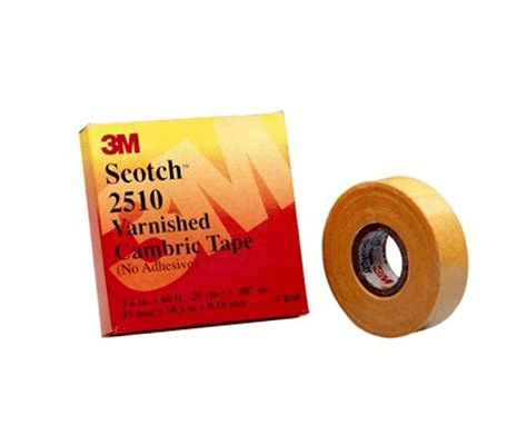
In the field we see varnished cambric tape used for motor connections.
image_qxkfrl.png

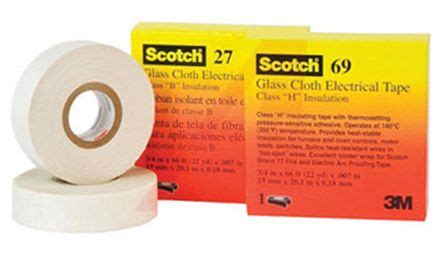
Another option is fiberglass tape.
image_bcujox.png

Wire nuts are convenient... but they are not the best method of making an electrical connection for a motor that vibrates.
There are two types of wire nuts:
One type has a rigid internal spring. Not good for motors or applications subject to heat cycling.
The better wire nuts have an expanding internal spring.
The expanding spring wire nuts are excellent for both vibration and for heat cycling.
With one contractor we made a policy decision to standardize on and only supply our crews with expanding type wire nuts.
If the better quality avoided one call-back a year, it would more than pay for the slight added cost.
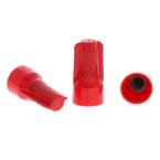
image_tnsqur.png

Product Overview
The B-CAP's low profile design works in those hard-to-reach spots comfortably, especially when retrofitting or updating. With an expanding interior spring, this connector accepts a wide range of wire sizes and combinations. Classic Fin design provides a secure grip for extra leverage on maximum wire combinations.

Bill
--------------------
Ohm's law
Not just a good idea;
It's the LAW!
 
Hi mellomain,

Usually, this three phase motor protector are manufactured for protecting motors from 1/2 hp to 5 hp. In your case this is dual voltage NEMA motor and note this is a 12 lead motor (not a 9 lead) also final connections are made through the overload protector that is designed with normal close contacts. Then the HV Connection will be 1-Y and the LV Connection will be 2Y. Protection device will sense the current by the lines and trips if overload occurs. I believe the attached drawing might help.

Best Regards

Petronila
 
Please take a look at the relationship between the 4, 5, 6 terminals and the P4, P5, P6 terminals.
Your diagram does not seem to agree with the diagram that the OP posted.
On the OP diagram, the o/l heaters seem to see twice the current on the low voltage connection as they see on the high volyage connection,
On your diagram, one phase sees 2 times current and two phases see 1.73 times current.
I would not use either of those connections if those are overload heaters as indicated on the drawings.
On the other hand, the protection may react to the motor temperature and the heaters are shown in error.

Bill
--------------------
Ohm's law
Not just a good idea;
It's the LAW!
 
Hi, Waross,
I have a different opinion.
- In normal conditions points 4; 5; 6 (on the internal protector) will form an internal Wye, regardless of the connection (Low or High Volt), ie. 4-5-6 are joined together.
- The same current flows through the "heaters" 1-4; 2-5 and 3-6 in both cases.
At High Volt it is total phase current, at Low Volts it is half of total current, because "heater" 1-4, for example, is connected in only one of two parallels.
In addition, it is a bimetal-based protector and it reacts to increased temperature, whether caused by increased current or something else.
Am I right?
Visit us
 
Normally on the low voltage of a nine lead wire, there are two wye connections.
The T4, T5, and T6 wye connection and the internal connection of what, on a twelve lead motor, would be the T10,T11 and T12 connections.
This motor, on the high voltage connection, the L1 current flows through the protector.
On the low voltage connection, L1 current is twice the high voltage current, but still flows through the protector.
The connections are asymmetrical so the other two legs of the protector see 1.73 times the high voltage current.

The diagrams for the protector show both a heater and an overload relay symbol.
The heater can not be calibrated to provide running protection at both voltages.
It may provide stall protection.

On the other hand, the diagram linked by the OP shows T10, T11, and T12 internally as well as T14, T15, and T16 as connections on the protector.
The internal connections of the protector are not shown but it is quite a safe assumption that the protector leads bypass the heaters internally and connect only to the overload relay section.
This is the same wiring scheme and protection philosophy found in very old "Generator Circuit Breakers"
A "Generator Circuit Breakers" was a specific device and not just any circuit breaker on a generator.
A "Generator Circuit Breakers" was a nine terminal circuit breaker:
Three line terminals,
Three load terminals,
Three terminals connected after the thermo-magnetic section but before the operating contacts.
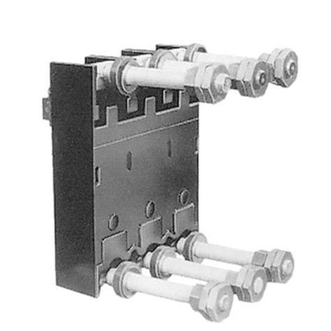
They were typically stud mounted moulded case breakers similar to this but with three more studs.
image_gz0o9r.png

The last "generator circuit breaker" that I encountered was about 35 years ago.
The set was old then.
I understand that it was a military spec from WWII that allowed one breaker to protect the generator at either of two voltages.
These breakers were obsolete decades before the internet, don't expect to find a picture online.
Be that as it may, the operating principle is applicable to theses motor protectors.
By the way, Keith, did you ever encounter such a breaker in the old railcar equipment?

Bill
--------------------
Ohm's law
Not just a good idea;
It's the LAW!
 
When taping bolted wire connections we first use a layer of the Scotch 2510 varnished cambric tape often called puncture tape in industry. Then, to build thickness we wrap with a self-fusing tape to form a ball, usually Scotch 23. Finally, for protection and oil resistance, a couple of layers of Scotch Super 88 to finish.
 
I agree completely for voltages below 2300 Volts.
For higher voltages it is recommended to put the self fusing tape or Scotchfil on first to eliminate voids.
If you ever had to re-connect a higher voltage motor, and scrape the Scotchfil off of the hardware, you really appreciate the base layer of cambric tape on lower voltages.

Bill
--------------------
Ohm's law
Not just a good idea;
It's the LAW!
 
Here is a picture of a "Dual Voltage Breaker".
I have seen this called a "Generator Breaker" in other texts.
dual_voltage_breaker02_2_hubvwa.jpg

This is probaly similar to the arrangement of the motor protector.
To compare this to the motor protector consider that the lines would be connected to the windings and the wye point would be formed by shorting the "A" studs together.


Bill
--------------------
Ohm's law
Not just a good idea;
It's the LAW!
 
It is now better visible what I was talking about.
It is obvious that at Low Voltage connection only half of the current flows through the "heater" of protector.
Consequently this type of protection can be used at dual-voltage, 3-phase motors but only in Wye connection.

Winding Design and Electric Motor Repair

AC_Windings_rosxt5.png
 
It is now better visible what I was talking about.
It is obvious that at Low Voltage connection only half of the current flows through the "heater" of protector.
Consequently this type of protection can be used at dual-voltage, 3-phase motors but only in Wye connection.
Yes I agree.
As far as the wye connection is concerned, NEMA dual voltage integral HP motors are almost universally nine lead motors internally connected in wye.
There are some delta connected nine lead motors.
The choice is a design consideration and a designer wishing to incorporate this type of protection will choose to design a wye connected motor,
12 lead NEMA motors are special purpose and are extremely rare.


Bill
--------------------
Ohm's law
Not just a good idea;
It's the LAW!
 
Wow - thanks for all the great responses. We didn't really need physical connection directions. We always use lugs, mechanical fasteners, void fill material, and usually design a raychem cover.
The rest of the story is we have to remove the overload protector (its testing does not meet our specifications). After removal, I originally planned to reconnect point 1 to 4, 2 to 5 and 3 to 6. Then connect power as indicated to T1, T2 and T3. But then I started second guessing that idea because the dwg shows no connection(s) making it Y or Delta. It is is just 3 lines and no complete ckts. So what is there that I am not seeing?

If if remove the overload device, should 1, 2 and 3 be connected together or remain tied to T14, T15 and T16 which appear to do nothing?

Man is troubled by what might be called the Dog Wish, a strange and involved compulsion to be as happy and carefree as a dog --- James Thurber
 
The wye connection was formed inside the protector.
Connect T10, T11 and T12 together to form the wye connection.
That is the standard twelve lead connection.
If the leads are not numbered, the winding ends that connected to the protector were T10, T11, and T12.

Bill
--------------------
Ohm's law
Not just a good idea;
It's the LAW!
 
Excellent. That is basically what I originally told them to do but then started having second thoughts after noting the dwg did not show that T10, T11 and T12 (overload points 1, 2 and 3) were tied together.

Man is troubled by what might be called the Dog Wish, a strange and involved compulsion to be as happy and carefree as a dog --- James Thurber
 
If you want to bypass the OL heaters (don't know why you would want to bypass OL protection), simply jumper 1&4, 2&5 and 3&6 with cables of right size.

Muthu
 
If T10, T11 and T12 are not readily available, short P4, P5 and P6 together.
That will leave the heaters in the circuit but will bypass the contacts of the protector.


Bill
--------------------
Ohm's law
Not just a good idea;
It's the LAW!
 
Status
Not open for further replies.

Part and Inventory Search

Sponsor