Continue to Site

Eng-Tips is the largest engineering community on the Internet

Intelligent Work Forums for Engineering Professionals

  • Congratulations waross on being selected by the Eng-Tips community for having the most helpful posts in the forums last week. Way to Go!

Plot Result In A Cylindrical Coordinate in COMSOL 1

Status
Not open for further replies.

FEAppp

Geotechnical
Mar 27, 2020
24
Hello, I want to visualize the stress tensor in the cylindrical coordinate. Currently, I have the output from a 3D solid mechanical model. The expression I choose is solid.sx, solid.sy, solid.sz and etc. However, these are all plotted in the global coordinate. I want to visualize the result in the cylindrical coordinate.

I also tried to define a cylindrical system and selected it in the linear elastic material (solid mechanics). And then visualize the result in solid.slxx, solid.slyy and etc. But the thing is: the stiffness matrix I input for anisotropic material is based on the global coordinate. So if I selected the cylindrical system in the linear elastic material (solid mechanics), the calculated result give me a wrong output.

SO I want to know whether there are some other ways to visualize the stress in the cylindrical coordinate.

Thanks.
 
Replies continue below

Recommended for you

Try this:
- solve the simulation without local coordinate system
- define cylindrical CSYS and specify it in the Linear Elastic Material node
- instead of solving use "Update Solution"
 
Hello FEA way,

It is also not correct. When I update solution, the original solid.sz solution changes. However, this stress tensor shouldn't change since it's correspond to the global coordinate stress tensor. That being said, I still think that the comsol treated my stiffness matrix I input is based on the cylindrical csys after I update solution.
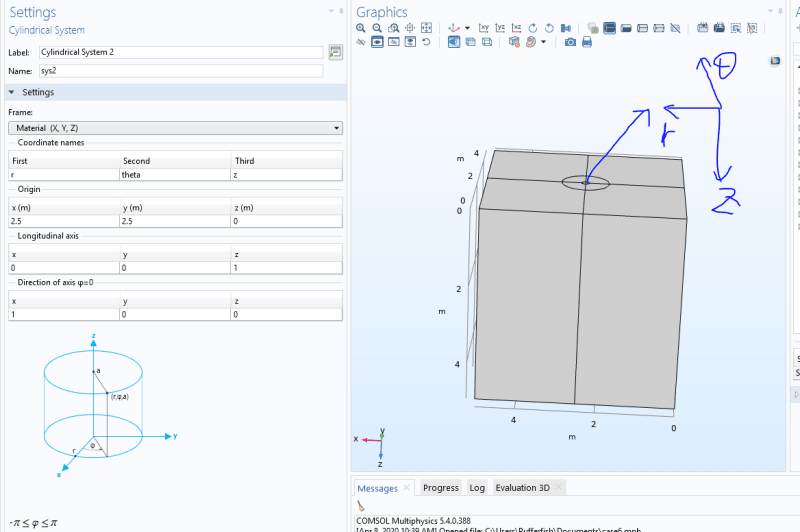
I defined the csys. Attached.
Do you have any ideas?
def_txjri1.png


Thanks,
Wenjing
 
This should work:
- set Linear Elastic Material --> Coordinate system: Global coordinate system
- run the analysis
- in the Expression field of the stress plot type: solid.sz*sys2.T33

Second term in this equation is coordinate transformation to local coordinate system named sys2 for the 3rd component. You can find it under Model --> Component 1 --> Definitions --> Cylindrical System 2 --> Coordinate transform to system (sys2).
 
Thanks FEA way, it works for z component!
But what about I want to see the radial stress, sigma_rr?
I tried to use solid.sx*sys2.T11
But the result I got is incorrect.
Do you have any ideas where I did wrong?
Thanks a lot.
 
It seems that for radial and tangential components this is more tricky. These formulas should work:

- for radial component:

(x^2*solid.sx+2*x*y*solid.sxy+y^2*solid.sy)/(x^2+y^2)

- for tangential component:

(y^2*solid.sx-2*x*y*solid.sxy+x^2*solid.sy)/(x^2+y^2)

Axial component will be simply solid.sz
 
Hello FEA way,

Thanks a lot! It works~

Wenjing
 
Status
Not open for further replies.

Part and Inventory Search

Sponsor