Continue to Site

Eng-Tips is the largest engineering community on the Internet

Intelligent Work Forums for Engineering Professionals

  • Congratulations IDS on being selected by the Eng-Tips community for having the most helpful posts in the forums last week. Way to Go!

PMDC motor winding 2

Status
Not open for further replies.

Stupidspencer

Mechanical
Nov 10, 2015
6
I need to re-wind a PMDC motor and have a few questions.
The motor I need to wind is a 2 pole (two brushes and magnets) with 16 armature segments.
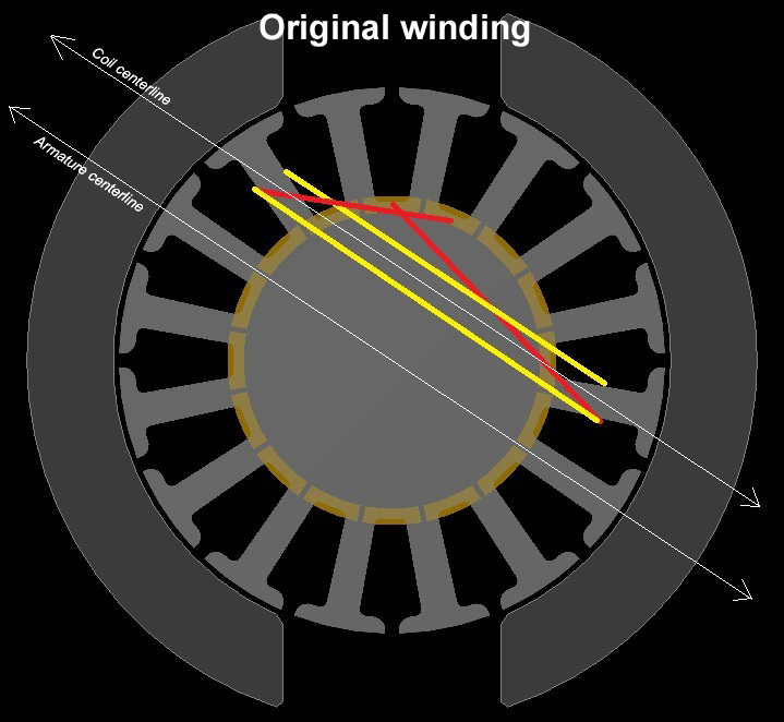
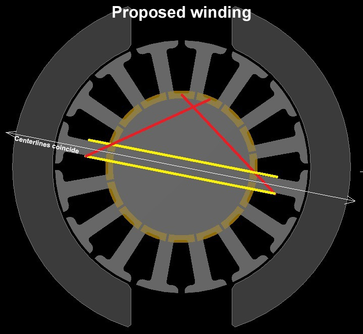
I have noticed that every electric motor I have worked on, including this one, is wound asymmetrically. Each of the original coils on this motor spans 7 segments. I would think that it should ideally span 8 segments (1/2 of the 16 segments) to create a coil that has poles that line up with the permanent magnets. Am I correct? The only reason I can think it was wound as it was would be to facilitate automatic winding in production, but at a slight loss of performance. Since I will be re-winding the motor by hand, and do not have the limitations of flier winding, will I increase this motor's performance by winding around 8 segments?
Thanks for your input.
 
Replies continue below

Recommended for you

Anybody?

I'm a new member, but I am NOT a student looking for easy homework answers. I AM an engineering professional whose education did not include electric motor design. I have been searching for the answer to my question for a few weeks now, and even the local motor repair shop did not have an answer for me. That guy said "You must follow the same winding pattern that was there before", which I know to be BS. I read a technical article that suggested that modern electric motors aren't necessarily wound optimally due to automatic winding limitations. Hence my legitimate question: Is there a better way to wind PMDC motors when no manufacturing method limitations are present?
 
Hi Stupidspencer

If your motor was working proper before the failure and you don´t want troubles just copy the winding.

To avoid efficiency issues preserve the lenght of the coils and use the same wire size.

One repair shop can improve an original design when can decrease safetely the coil lenght and increase the wire size, if you can do that do it. This good practices would help you to improve motor efficiency. Don´t overheat the core and use the same insulation class or higher.

Regards

Carlos

 
Thanks for your input, Carlos.
I might be on the wrong track because I was gonna do the opposite of what you suggest. However, there is another factor I forgot to mention. The motor was originally designed to run at 100% duty on 24VDC with a fixed load. However, I will be running it with varying load at up to 36VDC.
To handle the extra voltage, I figured I needed more resistance in the coils and so decided to re-wind it with wire that is 1 gauge size higher. From what I have read, that change will cause a drop in amp demand, but will increase the magnetic flux density, so the torque output will be roughly the same or maybe a little less. But the higher voltage will provide the higher RPMs needed which is worth the trade-off. The original configuration was 21AWG 155C wire - 9 turn double (each segment is wound with 2 parallel 9 turn coils). I am going to wind it with Essex 22AWG 200C wire - 12 turn double which should give me 10% more copper fill (There was plenty of extra space for more copper in the original configuration).

But none of this really answers my question.
Is there a reason that the motor was originally wound such that the armature coils' poles do not directly line up with the permanent magnet poles?
Here are 2 pictures illustrating my question:
The red lines represent the wire path to and from commutator segments. The yellow represents the coil winding.
motor_config_original_sekmtd.jpg
motor_config_3_y9kx5x.jpg


I did spend a little time drawing the coils in MS Paint, but I already had the armature and other parts modeled in CAD to aid in calculating the winding fill area.
 
OP said:
From what I have read, that change will cause a drop in amp demand, but will increase the magnetic flux density,
You may want to re-read that.


Bill
--------------------
"Why not the best?"
Jimmy Carter
 
@Waross, you are focusing on something that is not related to what I actually want to know. The book I have goes into a lot more detail than I want/need for this project and is quite confusing for someone who is not dedicated to the field of electric motor design.

In case anybody else wants to comment, let me state my question once again:

Why do motor windings not span half of the total armature segments?
Stated another way: Why are the coils' poles off center from the permanent magnets?
 
I have no answer to your question, but if you find that every motor is wound contrary to your theory of motor winding it is much more likely that your theory is wrong than that every motor is miswound. Maybe as simple as the asymmetry is necessary to get the thing to start spinning in a known direction at start. That certainly seems to be worth a bit of theoretical loss of efficiency.
 
I answer not for your benefit but for the benefit of others who may be reading this.
You have made several questionable statements and/or assumptions.
1. "a drop in amp demand, but will increase the magnetic flux density" Not in the real world.
2. You seem to be using the terms winding and coil interchangeably. Not so. A winding is a group of coils. The difference is important.
3. You assume that the use of fractional pitch is a design compromises to facilitate automatic manufacture. Not so. That pattern of winding has been around for a lot longer than automatic winding machinery.
But winding pitch is what you are asking about. Winding pitch is a design compromise, but not to facilitate automatic construction.
A description from "Industrial Electricity" by Nadon and Gelmine. Originally published in 1939. Both Nadon and Gelmine worked in the training department of the Ford Motor Company, and Gelmine also lectured at the University of Detroit.
Fractional pitch:
Nadon and Gelmine said:
If the pitch is too small, an appreciable reduction in generated EMF Results.
(in a motor, back EMF)
However
Nadon and Gelmine said:
The fractional-pitch type of winding is in general use, because it produces less sparking and because it requires less copper, which means lower armature resistance.
It seems as if this design compromise may improve performance while reducing the amount of copper required.
That said, You assume that you know better than the experts.

Bill
--------------------
"Why not the best?"
Jimmy Carter
 
waross said:
That said, You assume that you know better than the experts.
Absolutely not! I thought I was asking the experts rather than telling them. And it seems that the experts have answered. Thank you for that, waross, despite being very condescending in presenting that information. I said "from what I have read..." to imply that this is new information to me and that I may have misinterpreted it. And I will read it again.

Not that it matters, but I believe you (waross) interchanged "coil" and "winding" in your last post. I'm not the expert, but it was my understanding that a winding is a loop of the wire that makes up a coil. According to Wikipedia; "The wire or conductor which constitutes the coil is called the winding". So it looks like neither of us were quite right. A winding is not a group of coils, nor is it an individual loop within a coil. A winding is the wire that makes up the coil and an individual loop in the coil is a turn. Are we all cleared up on this?

I will always admit I am wrong when presented with undeniable proof of such. In a classroom, I will take what I am taught as fact, but the internet is full of idiots, posers, and know-it-alls, and I am hesitant to accept the information they provide as factual until they show that it is more than just their opinion. Its how I prevent myself from becoming infected with their idiocy. [thumbsup2]
 
Or, perhaps Wikipedia has it wrong in this application. When we've had generators rewound, they ship a whole bunch of identical coils to the site. Then the coils are installed and connected to form the windings.
 
I agree with the Wiki entry on the definition of turns and coils but, in my industry at least, the winding is a group of interconnected coils.

The idea that the wire which forms the coil is the winding doesn't make much sense. On a drum it is just wire. Formed into a turn is it still wire, or is it a winding? Or does wire only become a winding when there is more than one turn present? It's a very poorly defined explanation, and contrary to the accepted use of the term 'winding' within industry.

In a classroom, I will take what I am taught as fact, but the internet is full of idiots, posers, and know-it-alls, and I am hesitant to accept the information they provide as factual until they show that it is more than just their opinion. Its how I prevent myself from becoming infected with their idiocy.

In a classroom I will listen and keep an open mind. Lecturers are frequently clever people, but they're not infallible. Good lecturers will have no problem being politely challenged, and will explain their position.

The internet is indeed full of idiots, posers, and know-it-alls. I am trying to decide which of the three categories you fit in, and I think I have ruled out 'poser'. If you can provide undeniable proof that you're not infected with idiocy then I guess that leaves 'know-it-all', but until I see that proof I will keep an open mind. ;-)
 
Davidbeach: If you think Wikipedia has it wrong, I encourage you to edit the definition. Wikipedia definitions are created by its users.

ScottyUK: I might be an idiot. I'm not sure. Idiots are usually too stupid to realize their own stupidity.
 
All of us have room to learn, and this is a very good place to do so. That's the reason why most of us come here. :)
 
Dear Stupidspencer,
I presume you're new on this forum. I'm ashame to see you showing disrespect to some of the gurus of this forum. Take your time and peruse through the various subjects and you'll appreciate the worth of people like Waross, Davidbeach, Jraef, ScottyUK and others.
These people are devoting their precious time and are sharing their knowledge and experience to members of the forum. I say hats off to them and god bless.
Cheers
Guardiano
 
I think that the wire is wound offcenter because the armature`s shaft stands out at both ends so it needs room
 
An armature winding that includes 7 of a possible 8 segments is called a fractional pitch winding.
I don't know how long it takes for a winding scheme to achieve "General use" but fractional pitch was in general use in 1939. (Long before Wiki by the way.)
In case anyone missed the fine print:
Quote (Nadon and Gelmine, Industrial Electricity copyright 1939)
The fractional-pitch type of winding is in general use, because it produces less sparking and because it requires less copper, which means lower armature resistance.

Bill
--------------------
"Why not the best?"
Jimmy Carter
 
Status
Not open for further replies.

Part and Inventory Search

Sponsor