Continue to Site

Eng-Tips is the largest engineering community on the Internet

Intelligent Work Forums for Engineering Professionals

  • Congratulations KootK on being selected by the Eng-Tips community for having the most helpful posts in the forums last week. Way to Go!

Pneumatic problem 1

Status
Not open for further replies.

gersen

Materials
Nov 14, 2017
27
Hi,
I have a problem with one of my project:
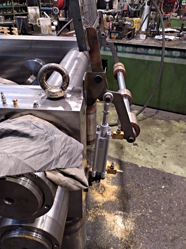
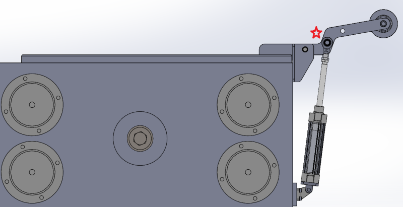
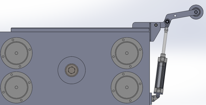
I'm building a movable cover for my machine, see image below.
I want to move this with a pnematic cylinder. The cover is normally opened and the cylinder need to push it colsed.
The problem is that when I give pressure, the cover close way too fast, I think almost 1 m/s. The cover is 60 Kg so this is very dangerous.

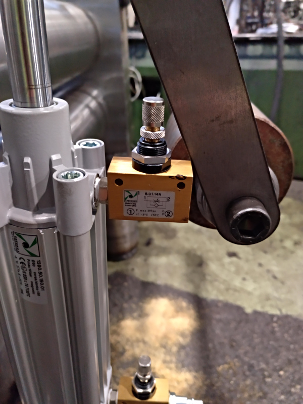
I have tried a flow limiting valve on the upper chamber but I don't have any improvement (the air in this chamber get compressed without any difference in the speed of the cylinder).

I have no experience using pneumatic system so any halp is greatly appreciated.
Thank you

Immagine_wy1lp9.png
 
Replies continue below

Recommended for you

Did you put the flow control valve on the cylinder, not on the air line some distance away from the cylinder? Facing the right way? You may want to consider running the top of cylinder to a regulator controlled surge tank so you can maintain pressure that's only a little lower than what's needed to close the lid.
 
Your arrangement won't work well with a pneumatic system...

The leverage from the cover acting on the cylinder will drag the cylinder out. Even if you add some flow controls to the cylinder, I think that the mass of the door combined with how close the cylinder is to the fulcrum, the door will drag the cylinder out.

Move the cylinder or use a hydraulic system...

Have you done the equations to calculate the forces in this system?

 
IMG_20180205_170350_462_pkjchw.jpg


HPost said:
The leverage from the cover acting on the cylinder will drag the cylinder out.
With the weight on the rear the center of mass works agaist the cylinder (see image below), the lid is normally open.
Immagine_juxapp.png


HPost said:
Have you done the equations to calculate the forces in this system?
No, I had this cylinder in stock so I only made sure its force was enough to lift the cover (Ø50 bore).
My problem isn't the cylinder pushing force, but its speed.

HPost said:
use a hydraulic system...
I thought about that(...we produce hydraulic cylinders) but my boss want to use air of the centralized line.

John2025 said:
Did you put the flow control valve on the cylinder, not on the air line some distance away from the cylinder? Facing the right way?

Yes, they are good

IMG_20180205_170359_426_jjtbl8.jpg


Maybe I need to add some more wheigt on the rear
 
We have machines with a similar design that open and close ovens with elec heaters. One of them has very fragile heaters so we needed to close softly. We added a hydraulic cylinder with a resevoir and flow controls in addition to the air cylinders that supply the force. The hyd just smooths the motion, no pump, etc. Maybe that's what you need.
 
 http://files.engineering.com/getfile.aspx?folder=969ee0bc-47a4-4c7d-b368-33570562cffc&file=20180205_110408.jpg
For the flow control valve to be able to control the speed of the cylinder the cylinder must be fully pressurized on the rod end before you start to close the lid. This is a double acting cylinder and there should always be full pressure on one end or the other. The valve controls how fast air bleeds out of the cylinder. If there is no air pressure to start with, the valve does nothing.
Hydraulic fluid is much less compressible than air so position control is far more "rigid". 100 psig air is much more "rigid" than 0 psig air.
 
I'd say the problem is that the pressure starts at zero and doesn't build enough pressure to slow the motion until the cylinder has retracted far enough to compress the air inside the cylinder. By then it's too late since the geometry of that linkage is going to want to close fast at first and then slow down as the lid closes. That's why I suggested either maintaining back pressure in the exhaust side or using a hydraulic cylinder that doesn't need to compress anything.
 
What I mean to say is that mass of the cover will pull the cylinder up.

If you close the flow control on the rod end of the cylinder and pull the cover down, how far does the cover move before the pressure in the rod end is high enough to hold the cover?

My bet is that the cover will go all the way down.[pre][/pre]
 
A trick you can use is put a pressure relief valve at the outlet of the solenoid. This valve could be preset to 2 bar. This way the rod chamber never gets empty and the flow regulator has air to regulate.
I know this is not a very precise way but I have use it once and worked for me.

Best regards
 
I would look at a "pneumatic over hydraulic" system where the pneumatics provide control and motive force for a small hydraulic system.

[bold]David Simpson, PE[/bold]
MuleShoe Engineering

In questions of science, the authority of a thousand is not worth the humble reasoning of a single individual. Galileo Galilei, Italian Physicist
 
I appreciate very much your help.

I tried adding some pressure on the rod side and applying the flow regulation valve on the inlet. Now I have a good speed for 2/3 of the stroke but it greatly reduces at the end (when the air in the rod side is compressed).
I now have to figure a way to reduce the lenght of this reduction in speed.
 
I don't think you're going to be able to change the slow final closing. If you think about how far the lid moves with a given cylinder motion throughout the stroke you'll see that even a constant cylinder speed will generate that fast to slow lid motion, unless you're want to change the linkage itself.
 
For the air over hydraulic idea...

Parker have a unit called a hydro-check. Web search hydro check for more...
 
It is not clear that you have any real problem except a lack of understanding of pneumatic design. The pictures show that the unit is not connected to control valves and you are applying air manually to try to check for proper operation. Install a 4-way valve and test it properly.

To start there should be full 100 psi air in the rod end and no air pressure on the other. When you switch the valve to close your gate, full unrestricted flow of air enters the bottom of the cylinder and comes to equilibrium with the air pressure on the rod end. The piston should only move after air is exhausted slowly from the rod end through the speed control valve. The air pressure in the rod end will stay at about 100 psi until the piston meets a mechanical stop, at which point the pressure in the rod end will drop to zero. The pressure in the bottom of the cylinder will stay at 100 psi as long as the gate is closed.

When you switch to open the gate, the rod end will quickly pressurize with an unrestricted flow of 100 psi air, but the piston will not move until air is slowly exhausted through the flow control valve on the bottom of the cylinder. The air pressure on both sides of the cylinder will stay essentially the same and constant on both sides of the piston until it hits a mechanical stop, at which time the air pressure on the bottom of the cylinder will drop to zero and the air pressure on the rod end will stay at 100 psi as long as the gate is open.

Now in reality there will be differences in pressure across the piston due to the load on the piston rod but this will be small if the load is not near the capacity of the cylinder. Your gate has counter-balance weights to keep this load small, so you should have no problem with this.
 
Here are a couple additional thoughts:

You may benefit from a pressure regulator on the supply air to the bottom of the cylinder to lower the supply pressure. You have a relative large rod diameter compared to piston diameter so the piston areas are different. This causes a pressure amplification effect where putting 100 psi of pressure below the piston will compress the rod end air to a greater pressure, say 120 psi. This will cause an initial jump in the piston position when the valve switches to "close the gate" (due to the rod end pressure jumping from 100 psi to 120 psi, even though your supply pressure is only 100 psi).

If you have long runs of tubing the flow resistance will cause problems, which a "quick exhaust valve" will address.

Consider what happens when you first apply air pressure to your machine. You do not want anything moving and creating a safety hazard. With no air pressure the machine should be in a fail-safe position. Accomplishing this could be the most complicated part of designing the controls.
 
Here is an idea and that would be to increase the weight of the roller arm (right side of the cylinder) in order to balance the weight of the door. Counterbalance is used on lift and bascule bridges and reduce the size of the motors involve in the operations of these bridges. For an experiment hang some weights on the handle bar with perhaps with the existing cylinder the system would work. If adopted, perhaps the fulcrum pin may need to make stronger
 
Status
Not open for further replies.

Part and Inventory Search

Sponsor