Eng-Tips is the largest engineering community on the Internet

Intelligent Work Forums for Engineering Professionals

Point load on small diameter pipe - Calculating "Squash" load

Status
Not open for further replies.

Jc67roch

Structural
Aug 4, 2010
76
0
0
US
I am designing a soldier pile wall with a steel w12x58 waler, and as desired by client, using proprietary 7" o.d. pipe helical pile piers, 0.408 inches thick, 80 ksi steel as the soldiers. I want to confirm that the concentrated reactions of the piles against the waler at the support points are low enough that the pipe piles won't "squash" under the load. If they are, I can place concrete on the pile interior to provide better resistance to squashing (issue is added cost). Is there a reference that provides calculation of this squash load for small diameter pipe? I found a ton of references for large diameter pipes (ala road culverts). Thanks! See sketch attached.
 
Replies continue below

Recommended for you

A simple check is ask a testing lab. Should be a simple set up and be done in a few minutes. Could even rig up a field test on pipe and rough load test using a calibrated hydraulic jack.
 
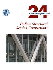
You should be able to find something in this doc to suit your needs. There's similar information in the CIDECT manuals and in research done by J.A. Packer who seems to be the alpha-researcher on this subject currently.

C01_cg8vst.jpg
 
Two or three approaches come to mind.
One, there are simple solutions for loads on a circular ring. If you assume your circular ring is a section of pipe, say 2 diameter or 3 diameters long, you can get a quick check. See Roark for equations.
Two, there are solutions for loads on cylinders as commonly encountered for nozzle loads on pressure vessels. Best handled if you have vessel software that includes this capability. You'd have to assume some finite load area, not a "point" load.
Third, it would potentially be a pretty simple finite element problem.
In any of those three cases, the main issue is that you could manipulate your assumptions a lot, so the solution may tell you more about your assumptions than it does about the physical problem.
On Item 2, be aware that the allowable bending stresses in some cases are taken very high, 2x or 3x yield, which is not necessarily what you'd expect.
 
Jc67roch:
Well, it’s actually not a point load, it’s a 10” long line load on the 7” dia. pipe, with a max. line load magnitude at the web ‘k[sub]1[/sub]’ area of the W12x58, and tailing off to the flg. tips. The weld btwn. the pipe pile and the WF is going to be, an almost impossible to make, flare-bevel weld, having to reach about 3” into the root. Why not take some 2” x .75” bar stock, 8” or 10” long, one on each side of the pipe and back to the flg. of the waler beam. Rip one corner off the bars at about 60° to kinda conform to the pipe shape, leaving a 3/8” bar edge land. This allows you to use fillet welds to the pipe sides and the waler flg. when the bars are pressed ripped corner to the pipe and rolled edge to the beam flg. This should pretty much eliminate the concern about the line load on the pipe.
 
Status
Not open for further replies.
Back
Top