Good morning,
I am confused on how to calculate the bonus tolerances of this drawing. I looked for similar examples in this forum, videos and manuals but I can find something quite similar. I am really hoping someone can help me to better understand these Position callouts.
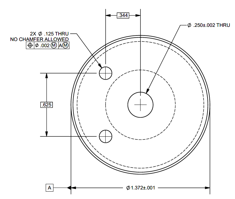
Do you combine the A) Tolerance Zone Diameter of a Position MMC applied with no datum reference + B) the Total Location Tol Dia of a Position MMC applied to a hole? I'm referencing ASME Y14.5-2009.
For example,
Drawing - Measured value
.344 - .346
.625 - .6246
1.372 - 1.3716
.125 - .126
The interpretation for A), would be Tol = Position tolerance + (measured value - (1.372-.001) = .002 + (1.3716 - 1.371) = .0026
Position = 2 x sqrt ( (.346-.344)^2 + (.6246/2-.625/2)^2 ) = .004
Which would make the part fail, since .004 > .0026
The interpretation for B), would be Total Location Tol Dia = Tolerance + bonus = .005 + 0.001 = .006
Same position, but now the part passes since .004 < .006.
My questions are, do you use interpretation A, B or both? If both, do you sum, rest or what do I do?
Thank you so much!
I am confused on how to calculate the bonus tolerances of this drawing. I looked for similar examples in this forum, videos and manuals but I can find something quite similar. I am really hoping someone can help me to better understand these Position callouts.
Do you combine the A) Tolerance Zone Diameter of a Position MMC applied with no datum reference + B) the Total Location Tol Dia of a Position MMC applied to a hole? I'm referencing ASME Y14.5-2009.
For example,
Drawing - Measured value
.344 - .346
.625 - .6246
1.372 - 1.3716
.125 - .126
The interpretation for A), would be Tol = Position tolerance + (measured value - (1.372-.001) = .002 + (1.3716 - 1.371) = .0026
Position = 2 x sqrt ( (.346-.344)^2 + (.6246/2-.625/2)^2 ) = .004
Which would make the part fail, since .004 > .0026
The interpretation for B), would be Total Location Tol Dia = Tolerance + bonus = .005 + 0.001 = .006
Same position, but now the part passes since .004 < .006.
My questions are, do you use interpretation A, B or both? If both, do you sum, rest or what do I do?
Thank you so much!
")