Eng-Tips is the largest engineering community on the Internet

Intelligent Work Forums for Engineering Professionals

Position Tolerance of a square feature on a disk

Status
Not open for further replies.

jdmmech

Automotive
Feb 5, 2015
16
0
0
US
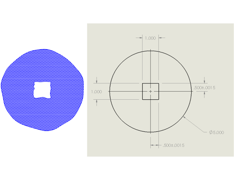
I have a disk that is inserted in a cylinder. A square sleeve will be inserted and welded to the square bore of the disk and I am trying to center the hole on the disk. Is a position tolerance the best way to do this? I have read that you can use position with any feature, not just a circle. Even though it is a square, the diameter callout still seems correct to me as the tolerance zone.

Otherwise, setting an X-Y tolerance on the distance to the centerline would give a similar result. I guess the only difference there is the square vs circular tolerance zone.

Is this correct? Thank you.

 
Replies continue below

Recommended for you

Yes, a circular tolerance zone of Ø.030 would be appropriate given the tolerances you show.

"Know the rules well, so you can break them effectively."
-Dalai Lama XIV
 
ewh -- what is it that we want to fall within that diametrical zone?

John-Paul Belanger
Certified Sr. GD&T Professional
Geometric Learning Systems
 
Derived axis/center of a square. Or better we use Concentricity?

"For every expert there is an equal and opposite expert"
Arthur C. Clarke Profiles of the future

 
Hi All,

I believe what John-Paul is getting at is how to deal with the form error on part surfaces:

SquareHole_sjra06.png


On the irregular hole shown, several different derived axes/centers are possible (as well as several different centerlines for the OD). Given the tight tolerances, the magnitude of the irregularities could be in the same ballpark as the tolerances.

I'm also wondering - why is the location tolerance for this hole so tight, if a square sleeve is going to be welded into it?

Evan Janeshewski

Axymetrix Quality Engineering Inc.
 
If I remember correctly, axis is derived from mating envelope and not the actual surface.

"For every expert there is an equal and opposite expert"
Arthur C. Clarke Profiles of the future

 
Yes, I realize that an axis is derived from UAME, so form wasn't the issue. (Thanks anyhow, Evan!)

But ... what is the axis? The center of the AME from the vertical walls and then the center of the AME from the horizontal walls, then taking the intersection of those two planes? Or maybe a perfect square that expands until it hits, what, 3 points? (This seems to be an "irregular feature of size" if I can throw that term in here.)

The standard would normally say in a instance like this to default to the boundary interpretation. Yet the OP doesn't want that because the thing has to be centered in a circular fashion.

John-Paul Belanger
Certified Sr. GD&T Professional
Geometric Learning Systems
 
Another funny question: how to produce two-directional tolerance zone (if there is no other choice) based on one single round datum feature?

"For every expert there is an equal and opposite expert"
Arthur C. Clarke Profiles of the future

 
If I can safely assume the usage of the part (big IF) I would say it would be the center point of the biggest perfect square that fits in the square hole. How to accurately convey that through appropriate language, though, I would have to think about more.
 
All excellent points, and I will answer what I can. This is a very simplified example of the actual part. We currently use a round sleeve but have had years of problems and I am now looking at a square sleeve. I have a few options, but I need to at least get this one quoted. We did have problems when the circular sleeve was not centered and the shaft would move and cause failures. I need that shaft to be as centered on that disk as possible.

There will be a chamfer on the square bore, and on the sleeve, and that is where it will be welded (currently only on one side of the disk).

We currently have a +.002" -.000" tolerance on the circular bore and a +.000 - .005" tolerance on the circular sleeve, so yes, pretty tight tolerances.

Measuring these tolerances relative to the OD seems tough to me as well. The real OD of this part is about 2'.

JNieman, that sounds like my end goal, but all relative to the OD. And yes, I am struggling to come up with best way to convey this.
 
Hi Jdmmech,

Can you explain the working of this assembly?
Just wanted to know whether concentricity between disc and sleeve is more important or perpendicularity between sleeve and disc face.
 
CH,

I'm not sure that your latest possibility works:
-The two directly toleranced width dimensions are not compatible with the profile tolerance (the dimensions should be basic)
-The position tolerance would only apply to one of the widths. I think it would need another position tolerance for the other width.

This gets into several gray areas. I'm not sure what happens when a position tolerance referenced RFS is applied to a width that is controlled by a profile tolerance. It's defined when referenced MMC, using the boundary position concepts, but I'm not sure about RFS.

Evan Janeshewski

Axymetrix Quality Engineering Inc.
 
Evan,

2X applies to both dimension and position. The frame can be moved to the right to make it more obvious, but it won't really change the meaning.

The square has 4 implied basic 90 deg angles and profile controls orientation of square sides to each other.

No, dimensions shouldn't be basic. No, the width is not controlled by profile tolerance.
In fact, when you see profile applied to feature without basic dimensions, it is clear indication that profile controls form or/and orientation.

 
CH -- you clearly made the profile "all around." So the width is being controlled by the profile tol. Thus, the dims have to be basic.

John-Paul Belanger
Certified Sr. GD&T Professional
Geometric Learning Systems
 
Sorry JP, but I see it the other way "around".

I don't specify "true" outline - I don't control "true" outline. But if you see it as possible ambiguity, what will happen if I replace "all around" with 4X ?

"For every expert there is an equal and opposite expert"
Arthur C. Clarke Profiles of the future

 
CH -- profile must be applied to a "true profile" per paragraph 8.2. But see other thread I'm starting for this off-shoot topic.

John-Paul Belanger
Certified Sr. GD&T Professional
Geometric Learning Systems
 
Just to put a bow on this...
Based on the other thread, we've apparently established that the size dims of this square slot do not have to be basic dims, even though there is a profile tolerance all around, right?

John-Paul Belanger
Certified Sr. GD&T Professional
Geometric Learning Systems
 
JP,

Well, I guess we agreed that there is no "absolute" requirement to always have basic dimensions associated with profile.
We also found out that the concept may be confusing for many people.

If we agree that profile can be used to control form, orientation, but not the size, what do you think would be the best way to do so?
It's not a trick question or attempt to start another war.

If we believe something may be right, but confusing, the natural thing to do is to look for better way.
Hense my question from Dec. 1 about only using "4X"

"For every expert there is an equal and opposite expert"
Arthur C. Clarke Profiles of the future

 
Status
Not open for further replies.
Back
Top