Eng-Tips is the largest engineering community on the Internet

Intelligent Work Forums for Engineering Professionals

Position tolerance on countersunk m8 bolt for thread fit 2

Status
Not open for further replies.

Verkstad

Mechanical
May 17, 2011
44
0
0
SE
Hi
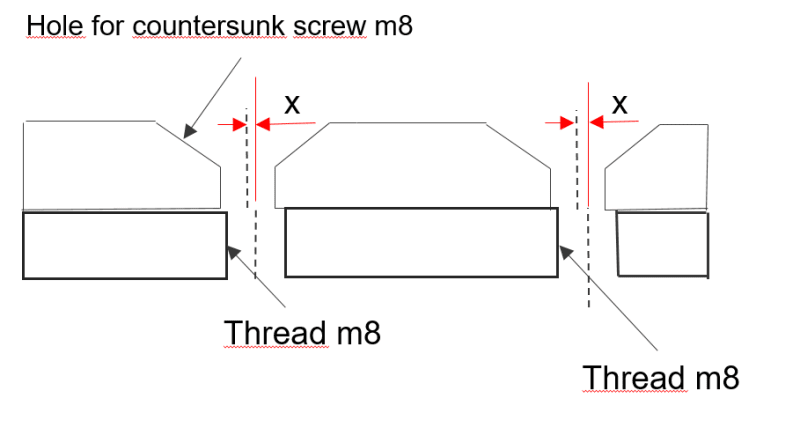
I have two parts one with countersunk m8 holes and one with threaded m8 holes. Since it is countersunk holes i can not move the screw to fit the center of the threaded hole. My thinking is to put position tolerance on the threaded hole and the countersunk hole to limit how much off center the holes can be. My question here is how much off center can allow the holes to go? See the distance x in the picture.

Kindly
Paul

Capture_p1cfa1.png
 
Replies continue below

Recommended for you

Hi

The hole with the c/Sk will be clearance on the M8 so subtract 8mm from the clearance hole size and take half of the answer that you arrive at, that will be how much the holes can be offset.
That assumes of course that the hole and c/Sk will be manufactured from a single tool.

“Do not worry about your problems with mathematics, I assure you mine are far greater.” Albert Einstein
 

The part with the threaded hole and the part with the counter sunk hole will not be manufactured together. The problem i see is that the countersunk shape of the hole will hinder the screw from moving sideway to compensate for axiell misalignment between the two parts.
 
After designing, building, and working around machines for over 4 decades I can say this with all my heart - I HATE HATE HATE countersunk holes. I have not specified a countersunk hole in many years. They ALWAYS lead to problems of binding or misalignment or some other related issue. In my mind, a countersunk hole is simply a sign of an inexperienced designer. There is almost always another better option. Of course, counterbored holes are an obvious choice, but sometimes there isn't enough material thickness to accept a standard screw head in a counterbore. Button head cap screws are a good option since they require a shallower counterbore depth than the standard SHCS. They have a flat contact surface and are very strong. Years ago I discovered another good option - low head socket head cap screws. They come in the same grades and strength as standard SHCS and make a very useful option. Get creative and AVOID countersunk holes in any way you can.

In regard to your original question, no matter what kind of tolerance you use on either hole, there will always be SOME misalignment. Perfect alignment is impossible. That means binding is likely.

There are two situations in which I might consider using a countersunk hole:
(1) If there is only ONE aligning hole in each mating part. (That situation is rare indeed.)
(2) If the mating thread was in an independently movable part, such as a nut.
 
I've often wondered the same thing. What is the material for the top plate? A soft material like aluminum would be somewhat compliant. A long bolt would help (shank bending) but maybe that's not possible.
 
C'sink holes are also used for if minimum clearance of mating parts. I have used lots of c'cink for space hardware where space between parts are small.
Misalignment of c'sink is usually because of poor machining and/or poor fixturing in the machine.

Chris, CSWP
SolidWorks
ctophers home
 
Hi verkstad

The screw clearance hole with the c/Sk was what I assume would be made with the single tool, I never mentioned the tapped hole being made with the mating hole and c/sk

“Do not worry about your problems with mathematics, I assure you mine are far greater.” Albert Einstein
 
Verkstad

it is very common to to counter sink in aircraft and done often. but in aircraft holes are generally drilled and counter sunk in line, in other words either matched drilled or
drill with a jig, or drill fixture, that way no possible way to misalign. your issue will not be the counter sink. as it is match drilled with the clearance hole. there is also tools
that drill and counter sink simultaneously. just put a note on the drawing, must be match drilled in line or equivalent. true position should be good.
the real issue will be to maintain the two hole in true position, the bottom and top. that's where GD&T is required.
 
What are the loads expected on the c'sunk screw?

If more significant than holding on warning or name plates I believe the design engineer should consider what JBoggs said.
 
It is stainless steel it is unfortunately a short shank 9,5 mm. The construction is made in a way that there are few options. Very tight with space. I do not know how much load the screw will be subjected to. This will be sent for calculation after that i will know.

But i guess what happens is that there become some plastic deformation and the joints gets a little bit weaker with a lets say max axiell difference of 0.1mm. The joint is not subject to fatigue which would be worse.

I think that many Engineers think that this joint is fine. Which makes it hard for me toder motivate changes, 0.1 in difference dont sound much.

But i will try to make counterbore holes and see what the structural engineer says.
 
"I wouldn't worry about a .4 mm offset. There will be enough deformation to handle that."
Deformation itself is not the issue. Ask the poor shmuck that has to remove those screws after they have been in that "deformed" position for a while. He will tell you that he nearly stripped the hex sockets trying to back them out. The problem has to do with geometry. Tapped threads have a single fixed centerline, and will pull a screw to that center. The conical bottoms of flat head screws also have a single fixed centerline. The two centerlines will NEVER match up. With flat bottom screws that is not a problem because each screw is free to "find its own exact center" (within its clearance hole) regardless of small inaccuracies in the hole pattern. This is not the case with flat head screws. Even the smallest misalignment will likely cause a bind, thus causing problems in removal. This is experience talking.

One usually sees this in mating machine components. As was pointed out above, if all you're doing is retaining some thin cosmetic part such as a label, this probably won't be an issue.
 
trick is to have a hole with plenty of clearance, and the screw will seat on the counter sink. thus no deformation. if it's more than that, then it's poor drilling.
 
"trick is to have a hole with plenty of clearance, and the screw will seat on the counter sink. thus no deformation. if it's more than that, then it's poor drilling."

I'm afraid you're misunderstanding my comments. The problem isn't the size of the clearance holes. Flat head screws will try to center themselves on the center of the conical surface regardless of the diameter of the clearance section of the hole. As they are tightened they will also try to center themselves on the tapped threads. The misalignment of the conical surface in one part with the tapped threads in the other part is the source of the problem. And making the clearance section of the countersunk hole larger will not affect that misalignment.
 
JBOGGS
I do under stand, in the old days there was a plaster master, every tool in the aircraft plant was coordinated to that tool.
soo drill jigs were used to keep the holes inline ,and if that was not good enough then it was matched drill.
to be that exact it takes a jig mill or jig grinder. a standard new cnc mill is very close. but not exact. jig grinder can hold
.0005 true position. but very slow and expensive. but in this case it appears to be a simple design. i dont expect trouble with it.
con complicated machines and designs thats, an other story and I agree.
 
Status
Not open for further replies.
Back
Top