Continue to Site

Eng-Tips is the largest engineering community on the Internet

Intelligent Work Forums for Engineering Professionals

  • Congratulations waross on being selected by the Eng-Tips community for having the most helpful posts in the forums last week. Way to Go!

Positional tolerance twice for same Stud

MPSU

Automotive
Aug 26, 2024
23
Hey everyone,

I'm working on a new drawing and came across something confusing.

  • Datum A is a plane.
  • Datum B is a stud, which has a positional tolerance on one side (without the Ø symbol).
  • On the next page of the drawing, the same stud is referenced again, but this time with a positional tolerance relative to A, B, and C datums.
My question is—how is this possible? If we've already established Datum B using the stud itself, how do we then check its position against itself in the next step?

I've attached pictures for reference. Would love to hear your thoughts!
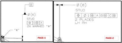
1738937161451.png
 
Replies continue below

Recommended for you

It is quite likely an error. Hard to say for sure without seeing the entire drawings. What is the reason for 2 drawing sheets? Is it just a very large or complex part, or are they possibly representing different versions of the same part?
 
It is quite likely an error. Hard to say for sure without seeing the entire drawings. What is the reason for 2 drawing sheets? Is it just a very large or complex part, or are they possibly representing different versions of the same part?
This customer is used to putting different dimensions on different pages. Eg: Datum callouts on one page, then profile callouts on another.
 
Sometimes for a pattern of similar features, one is a datum and the others are controlled back to it. They may be trying to do that here, but I don't think that it was done effectively. Is this an assembly drawing, and the studs are assembled into a housing? If so, one of the datum B references might be an attempt to refer back to the housing alone. In that case, I think it was still done incorrectly.
 
Sometimes for a pattern of similar features, one is a datum and the others are controlled back to it. They may be trying to do that here, but I don't think that it was done effectively. Is this an assembly drawing, and the studs are assembled into a housing? If so, one of the datum B references might be an attempt to refer back to the housing alone. In that case, I think it was still done incorrectly.
Yes, but they mention STUD in both of these. Not sure, thanks for the help. I am thinking they should have put Perpendicularity for Datum B, but then in the checking fixture it is the same thing since it would be going in a bush.
 
The control for the stud is in separate directions, one for datum feature [B ].

They give one control for the vertical position tolerance and a separate control for the horizontal position tolerance.

If they are grouping datum features on one sheet then that's why both aren't on the same sheet.

The check is of the right-left tilt of the stud relative to the horizontal plane from the vertical control; it's not checking the stud to itself, just one vector component of the stud to the other vector component.
Thanks Dave! I guess it makes sense. Another follow-up ques then, if the Stud dia is Ø06±0.5mm and positional tol is 0 at mmc, for gauging, the size of the bush would be 6.5mm on the vertical side and 7.5mm on the horizontal side (because of pg2). Right?
 
If that is a threaded stud and the standard is Y14.5 then the tolerance applies to the pitch diameter.

If that is an unthreaded stud, like a pin, then what you have stated sounds correct.
 
If that is a threaded stud and the standard is Y14.5 then the tolerance applies to the pitch diameter.

If that is an unthreaded stud, like a pin, then what you have stated sounds correct
Ohh! It is actually a threaded stud. How would you recommend gauging this dimension then
 
Typically the drawing, were they helpful, would say that the tolerance and datum feature applies to the OD, which won't have nearly so much tolerance as noted, to override the default pitch diameter. Otherwise it gets expensive to get a adapter that threads on and only touches the nominal pitch diameter.

I would also expect that the "0" tolerance would be enlarged, but that requires knowing what else is happening with the other parts and the function of the assembly to give an appropriate answer.
Okay. Last question then (sorry). There is gen. tol. (±0.5mm)on drawing for all Feature of size. Would this stud Diam (Ø6 mm) be considered as Feature of size, as shown in drawing?
 
It would not be controlled by the general tolerance because it is controlled by the thread standard, which will be far smaller than that, at least if the drawing is in accordance with ASME Y14.5.

This is the same as control of a standard thickness of plate or rod. If one says in the parts/materials block that the plate is 1.00 thk per ASTM or AMS then you go to the related spec for that material and it will tell you there what the material thickness tolerances are. Only if the drawing has that dimension as a firm callout, such as 0.950 to indicated the raw material is machined to a different dimension will the general notes apply.

Note that the diameters are given as reference rather than a firm callout.
Thanks!!
 

Part and Inventory Search

Sponsor