Continue to Site

Eng-Tips is the largest engineering community on the Internet

Intelligent Work Forums for Engineering Professionals

  • Congratulations SSS148 on being selected by the Eng-Tips community for having the most helpful posts in the forums last week. Way to Go!

Post-tensioning losses 1

Status
Not open for further replies.

Edvinas

Structural
Jan 25, 2017
12
Hi guys,

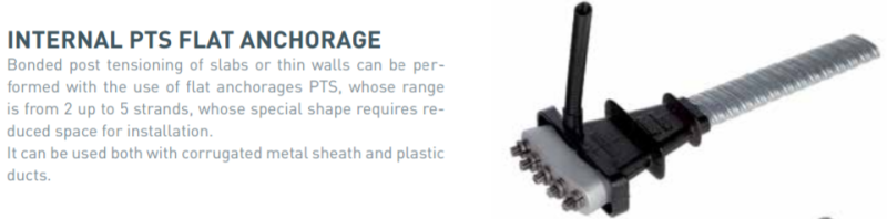
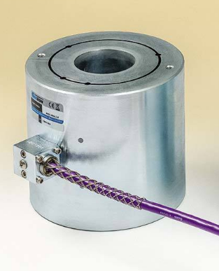
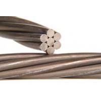
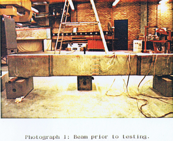
I am building a rectangular beam which will be post-tensioned and bonded, i have calculated my theoretical losses due to Friction, anchorage draw-in, etc. My question is this, is there any way of measuring the losses experimentally ? I know that you probably can't measure them individually but what about the total loss? Is there some type of equipment i can use which will allow me to measure the loss in the tendon?
 
Replies continue below

Recommended for you

They can (and have been) measured experimentally in a laboratory/test facility setting - especially friction and long-term relaxation/creep losses.

Wedge draw-in can be easily measured on site - it is an instantaneous loss so measure right off the back of the stressing ram.

If you have double live-end tendons then you can measure the friction between each two stressing ends by checking lift-off loads. If you have one dead-end and one live-end setup, then unless you install a load cell at the dead-end you will not be able to verify the force at this end.

I assume your bonded tendons are MULTI-strand tendons, or are they MONO strand stressed?

Any particular reason you wish to experimentally verify the PT losses? There is a lot of research from the 60's and 70' that covered PT losses.

 
Thanks for replying so fast, i should have given more information, i am building 2 post-tensioned beams for my bachelor degree thesis. The reason why i want to verify PT losses experimentally is because my beams will be very short(3.5m), making the losses very big, especially the anchorage draw-in (wedge draw-in) loss. The beam will be tested after 7 days, both ends are live ends and i will be using a PTSE anchorage system(Tensa post-tensioning), and the bonded tendons are like you said Multi-strand tendons. What exactly do you mean by lift-off loads ?

Thanks again
 
My undergraduate thesis (long time ago back in the 80's) did some unique lab testing on short PT beams (about 3m long) with testing to failure via over-prestressing. The work was NOT related to losses.

Lift-off testing is simply applying load to previously stressed tendon via the same stressing jack/ram and monitoring the pressure gauge when the wedges of the tendon "pop" and load transfers from the anchorage wedges to the tendon-proper.

In your case, I would recommend load cells (vibrating wire or electrical resistance type) at each end anchorage, and hooked up to a data logger you can continuously monitor actual force at each end of the tendon over the 7 day duration at a time interval of your choosing.

Or, if you wish to reduce wedge draw-in losses inherent with strand systems, use high-tensile PT threaded PT bar where bearing plates and compatible spherical washers and nuts are used to secure the PT force. However, PT bar will not work in conditions where the tendon has drape.

Are your multi-strand bonded anchorages flat type, or circular-section type? How many strands make up the tendon/s?
 
Anchorage is a flat type,7 strands make up a tendon, and i will only be having 1 tendon per beam. I have seen the those load cells you are talking about, my lab facility does not have them, i will look into it and try to obtain it. So from my understanding, having load cells connected at both live-ends of the anchorages i will be able to measure the total losses in the tensile strength of the strand in 7 days? Your thesis sounds interesting, initially i was looking to do something along those lines, however my lab facility has a rig that is limited to 100 kN.
 
Edvinas

Flat anchorage tendons are not normally Multistrand stressed. They are Monostrand. Each strand is stressed individually using a single strand jack.
Never seen a 7 strand flat anchorage personally, normal limit is 5 and I have heard of 6 but never seen one.
 
Rapt,

The anchorage system i will be using is very similar to "PTSE Flat Anchorage" system available on tensa post-tensioning manual, and the tendon is made out of 7 wire strands. Sorry i was wrong in saying multi-strand, the strand will be mono-stressed as my beam will only have 1.
 
Edvinas,

I agree with rapt, flat-type bonded anchorages typically cannot accommodate 7 strands. From Tensa's website, their flat anchorages accommodate max of 5 strands in a flat-type anchorage, whereby each strand is singularly stressed:

ptse1_ymnxzn.png


ptse2_yufgqn.png


This compares to a true multi-strand anchorage where all strands are stressed at the same time:

ptse3_jkv8i9.png


With regards load cells to monitor the dead-end and live-end PT forces (and hence determine losses between each end) the typical load cell is annular in shape, with different center hole diameter available from 25mm to 250mm, or larger.

ptse4_wrryma.png


With a flat-type anchorage, and its unique anchor-head shape, you maybe best to use a small diameter annular load cell and monitor one (1) strand only of the tendon, and use a barrel-chuck for the selected strand that is monitored (preferably the center strand).
 
Ingenuity,

Yes i see it now, the person that will help me with the actual stressing(due to safety reasons) showed me the "PTSE flat anchorage" system and said that it will be a 7-wire strand, he must have made a mistake, meaning it will be a 5-wire strand. Will try to get my hands on a load cell, thank you so much for your time and fast replies it really helped as i was a little confused.
 
Edvinas said:
thank you so much for your time and fast replies it really helped as i was a little confused.

You are welcome.

The terminology needs some explanation:

A single strand is made up of 7-wires (central straight king-wire and 6 outer wires is a left or right hand spiral lay) like the following:​

ptse5_tz6obg.jpg


For your PTSE flat-type anchorage there can be max of 5 STRANDS, each consisting of 7-WIRES. Note the subtle terminology use in BOLD.


If you want some info on load cells this manufacturer has good products, including very economical data loggers: Link


What is the proposed PT beam section size? To accommodate a flat-type anchorage you are going to need some decent beam width, and if you are limited my testing load capacity you may be best to explore options on how many strands you wish to place in your tendon to achieve the desired test results.
 
The preliminary beam section is b = 250mm, d = 350mm. I am still doing research, changing parameters, and becoming more familiar with PT, as we have not done much in lectures. The section size was another area i was looking in to and trying to decide if everything would fit e.g additional longitudinal reinforcement, shear links, and anti-bursting reinforcement. The construction stage of the beam will commence in two weeks time, which still leaves a little time for changes.
 
For such a small section size, you may be best to limit your PT to 2 or maybe 4 strands tendon. With 4 strands of 12.7mm dia 7-wire, stressed to 80% of UTS, that gives you a jacking force of 148 kN per strand (or 4 x 148 = 592kN for the tendon), which is a P/A of 6.7 MPa, which is of significant magnitude. You have to accommodate your anchorages, end-zone PT reinforcement, shear steel, and terminate your flexural mild steel rebar too - lots happening here in 250mm width.

What is the objective of the testing? Purely a 'build-it' and 'bust-it' learning experience, or testing a specific objective?

Also, check with your PT supplier, Tensa, they probably have load cells in their inventory to measure the PT forces described earlier.
 
The objective is to measure the losses experimentally of both beams. Beam 1 eill be HS(high stressed) while beam 2 will be (low stressed). I want to measure the losses occuring in both beams experimentally and compare them theoretically paying most attention to the draw-in loss which seems to be the most critical in short beams.
 
Based upon your username country code ("IE"), you are in Ireland. I am not familar with what type of stressing rams are predominantly used there, but in the North America they use hydraulic wedge seating, that uses a small internal nose that automatically pushes the wedges into the anchorage wedge cavity immediately prior to retracting the ram. Compare that to Australia, where simple spring-loaded noses are used to non-power seat the wedges. Check with your PT/stressing guy - he may have special 'short-tendon stressing equipment" that minimizes wedge draw-in losses.

You may be interested (maybe not?) but I dug out my 30 year old undergrad work. However, of no real relevance to your proposed testing. We used a 1 x 15.2mm dia. strand tendon (not grouted) that was continuously stressed until failure occurred via compression failure at midspan. Failure occurred at a prestressing force of 155 kN - in a violent manner that we captured via a 'trip toggle' to a camera away from the danger zone.

01261703_Page_002_mbwlwv.png


01261703_Page_001_lzygrp.png
 
That's very intresting, you used a parabollic shape for the tendon profile? I would have thought you could go beyond 155kN with a 15.2mm strand, having said that, your objective was to break it so you probably did not stress it in stages? That's very intreating, thanks for sharing.
 
Edvinas said:
you used a parabollic shape for the tendon profile?

Yes, a parabolic profile, with zero end eccentricities.

We were verifying the calculated 'strength at transfer' of prestressed elements so that entailed increasing the applied prestress jacking force in the strand tendon until the concrete compression strength capacity (not stress) was exceeded at the bottom section of the beam at midspan, closest to the maximum drape.

We purposely narrowed the beam section at midspan to only 95mm in width to make sure that as we increased the jacking force to maintain our desired compression failure, we did not get close to the tensile breaking capacity of the 15.2mm strand.

If we had of used a wider section, or stronger concrete, 1 x 15.2mm strand would not have had enough tensile capacity to achieve our objective mode of failure.

Good luck with your testing program.
 
Status
Not open for further replies.

Part and Inventory Search

Sponsor