Continue to Site

Eng-Tips is the largest engineering community on the Internet

Intelligent Work Forums for Engineering Professionals

  • Congratulations IDS on being selected by the Eng-Tips community for having the most helpful posts in the forums last week. Way to Go!

Power of AC electric motor with no data on tag 1

Status
Not open for further replies.

JerinG

Mechanical
Oct 18, 2009
99
I'm more from mechanical engineering side and I need some help here, because I can't get to proper power data needed for general use.

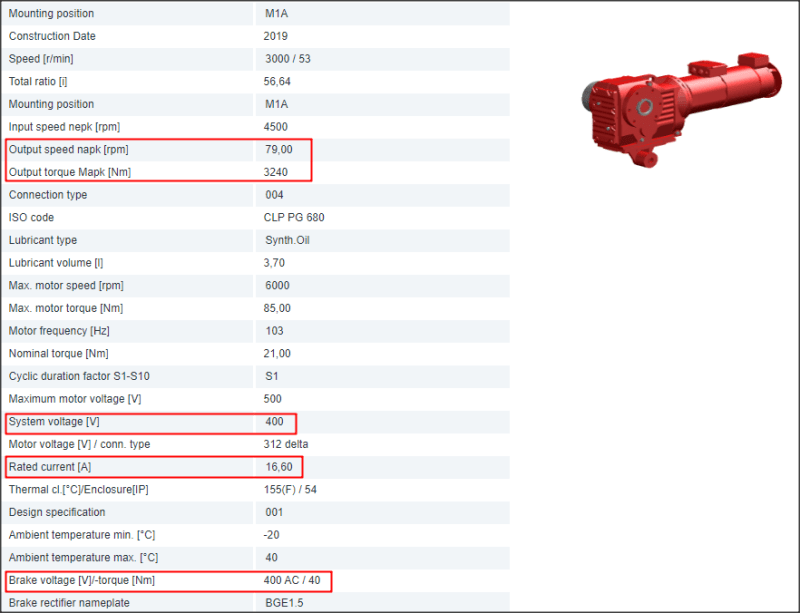
As mentioned, there is no power data on the tag, other data that is available is here:
2019_11_05-16_19_16_hkmziq.png


Now, if I calculate power from P = U * I = 400 V * 16,6 A = 6,6 kW.
If I calculate from output data on reduction output shaft, I get: P = M * omega = 3240 Nm * Pi * 79 / 30 = 26,8 kW.

Now that doesn't make sense. There is efficiency to take in account on worm gear, but power on reduction output is way off and it can't be larger than on reduction input.

What am I missing here? And one more thing. I assume that brake torque 40 Nm is for reduction input. That means that brake torque on output should be 2265 Nm.
 
Replies continue below

Recommended for you

Where to start.
Your power is 400 Volts x 16.6 Amps x √3 / 1000 = 11.5 kW (A factor of √3 must be used for three phase power calculations.)
Combined efficiency and PF may be around 90%, so 11.5 x 0.9 = 10.3 This is most likely a 10 mechanical kW motor.

Gear box; A stalled or accelerating motor may generate 200% to 300% of rated torque. The gearbox should be rated for maximum torque, not normal running torque.
eg: 28.6 kW / 6.6 kW = 433%. = motor maximum torque plus a safety factor.

Torque is proportional to the square of the current but limited by saturation. If your voltage is 10% high, the maximum current will be 10% high and the torque will be 21% high. Hence the generous safety factor. (At +10% voltage you are below the saturation limit.)

Frequency = 103 Hz. This tells us that this assembly is intended to be driven by a Variable Frequency Drive.
This strongly implies a three phase motor. There are rare exceptions, mostly for retrofits, not new designs.

Brake: The motor maximum torque is 85 Nm and the brake maximum torque is 40 Nm.
Considering the ratio between the motor running torque and the motor maximum torque, it looks as if the brake is adequate to hold the load, but may be unable to stall the motor. The brake should never be applied when the motor is powered.

Drive: The specs strongly indicate that this assembly is paired with VFD.
The motor specs, 400 Volts and 16.6 Amps are used to select the conductors feeding the motor.
The conductors feeding the drive will be similar, but the drive specs must be used to select the supply conductors for the drive.
I hope this explain the apparent confusion in the data.

Bill
--------------------
"Why not the best?"
Jimmy Carter
 
Hello waross and thank you for your short and straightforward answer. It will be very useful for me in the future.

I still have some questions. I hope you don't mind, maybe they will sound very simple to someone, but I need to clear some things up, because they constantly show up.

1) The motor is three phase, of course, I forgot to mention that and the manufacturer is SEW. Where did you get the power 28,6 kW and why did you compare it to 6,6 kW for maximum torque for gear box? Is this also the same as reading maximum torque 85 Nm and nominal torque 21 Nm, which gives a ratio 85/21 = 4,05?

2) Since my calculated power on the gear box output shaft is so big, I assume that I can't use Output speed (napk) and Output torque (Mapk) for gear box output shat power calculation or in other words Mapk isn't on output when napk is and vice versa.

3) If the motor power is 10 kW, then gear box output power is around 9 kW, if efficiency of 0,9 for gearbox is used.

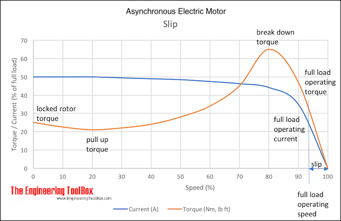
4) Where on AC motor torque curve is maximum torque 85 Nm located? Is that locked rotor torque or break down torque? It is logical that max. motor torque (85 Nm) and max. motor rpm (6000 rpm) can't be the same point on the curve. Nominal motor speed is 3000 rpm and this gives 21 Nm of motor torque. Is that correct and which point on curve is that? What is then input speed nepk that is 4500 rpm and why is it needed?
2019_11_06-11_28_39_pqs5wo.png


5) Nominal condition happens at 3000 rpm and 21 Nm. Is that at current frequency of 103 Hz or why is this frequency data important?

One last thing. I come across these kind of questions a lot when designing machines where these kind of motors are used. In this case one machine already exists and very similar one will be manufactured. But for mechanical engineering part of the design (structure calculation, loads, machine elements calculations, etc.), I need motor data and I also need to know how it works during machine operation, so I can use the data for correct design.
It is also hard to get some quick data from manufacturer catalogues, since there is a lot of this stuff. I also come across different electric motor manufacturers and it is hard to know the details of everything and where to find it.

I want to know more about this and I wonder if someone can point me to some litrature that can answer my questions. But not only basics, but practical use of different kind of electric motors - AC, DC, servo, etc. I'm also interested for web course like Udemy, Linda, Coursera, etc. that will cover this. If anyone can recommend anything, I will be very greatful.
 
Literature:
The Cowern Papers are a good starting place.
Cowern Papers
There is a problem with the graph that you have posted.
The numbers on the right-hand side are wrong.
Refer to the graph on age 3 of the Cowern Papers.
The most common motor, the design "B" starts with a locked rotor torque of about 150% and a breakdown torque of about 200%.
Starting current, when started Direct On Line is about 600%.
We used that curve for decades (the curve in the Cowern Papers), until VFDs became common. With a VFD it is still the same curve but a different way of reading it. More on that later.

Question #1 Where did you get the power 28,6 kW and why did you compare it to 6,6 kW for maximum torque for gear box?
Answer; I used your calculations. "If I calculate from output data on reduction output shaft, I get: P = M * omega = 3240 Nm * Pi * 79 / 30 = 26,8 kW."
The accuracy is not important. The point is that the rating is reasonable for motor breakdown torque plus a safety factor.
Think; "Sudden jam plus shock loading."

Question #2 Since my calculated power on the gear box output shaft is so big, I assume that I can't use Output speed (napk) and Output torque (Mapk) for gear box output shat power calculation or in other words Mapk isn't on output when napk is and vice versa.
Answer #A Use the motor rated torque times the gearbox ratio to calculate the maximum working torque of the output.
Use the maximum values to calculate forces and reaction forces. This will be short duration overloads, so that the machine does not destroy itself the first time it is inadvertently driven to breakdown torque.
Answer "B" This motor is a nominal 3000 RPM motor. That is based on the number of poles in the motor and the applied frequency.
It appears that the motor is controlled by a VFD with a maximum frequency of 103 Hz.
The nominal speed at 103 Hz is (3000 RPM / 50 Hz) x 103 Hz = 6180 RPM. The HP will be the same and so the rated torque at 6180 RPM must be (50 Hz / 103 Hz = 48.5% of the torque at 50 Hz.

Question #3 "If the motor power is 10 kW, then gear box output power is around 9 kW, if efficiency of 0,9 for gearbox is used."
Yes.

Question #4 " Where on AC motor torque curve is maximum torque 85 Nm located? Is that locked rotor torque or break down torque?"
Answer; The most important factor when a motor is driven by a VFD is not often emphasized. That is the slip.
What is the slip? A squirrel cage induction motor runs slower than synchronous motor. The slip generates the driving force.
A motor designed for 50 Hz may have a synchronous speed of 1500 RPM but a rated speed in a range of 1425 RPM to 1480 RPM
Or it may have a synchronous speed of 3000 RPM but a rated speed of 2850 RPM to 2925 RPM.
For our example we will work with a motor rated at 2900 RPM. The slip at full load is 3000 - 2900 = 1000 RPM.
100 RPM / 3000 RPM is 3.3% slip.
Now on the motor speed/torque graph, add the slip RPM across the bottom line. Note: using a percentage here will not work.
Now 100% of synchronous speed, 3000 RPM = 0 RPM slip.
A rated speed of 2900 RPM = 100 RPM slip.
We are concerned with the slip RPM
There is a fairly linear relationship between slip and torque, from zero slip RPM to 200 RPm slip.
100 RPM slip equates to 1.67 Hz. That is the frequency that the rotor sees, and that is the major factor determining the torque.
DOL starting. The slip is 2900 RPM and the torque is about 150% of rated torque.
As the motor accelerates, the torque follows the speed/torque curve.
When a motor is started with a VFD, a low frequency is applied.
As the frequency is increased from zero, the torque increases. As the motor starts to turn, the slip RPM drops and the current drops.
When reading the graph for a VFD controlled motor, the region of interest is from synchronous speed to the breakdown torque peak.
Notes:
1 Use slip RPM, not percentage.
2 100% speed is not the rated motor speed, it is the speed equivalent to the frequency applied by the VFD.
3 The load determines the torque that is demanded.
4 Hard to start loads may be supplied with about 200% of rated torque for starting duty when driven by a VFD. DOL will provide only 150% of rated torque.
That's enough for now.
Look this over and come back for more questions and clarifications.
Feel free to jump in with corrections, jraef.


Bill
--------------------
"Why not the best?"
Jimmy Carter
 
Hey waross,

Thank you for your effort and answers. I have to take some time to study this and the paper you posted link to. I will probably have to come back with answers some time later as you mentioned... [bigsmile]
 
Status
Not open for further replies.

Part and Inventory Search

Sponsor