Eng-Tips is the largest engineering community on the Internet

Intelligent Work Forums for Engineering Professionals

POWER PACK DESTRUCTION

Status
Not open for further replies.

JASGripen

Electrical
Feb 6, 2020
22
0
0
US
Any idea how a burnt up plastic power pack for a string of 277v LED fixtures can burn up half the relays in a lighting control board and then trip multiple 20A circuits and the 200A main.
I am thinking bad design - breakers should be after the lighting control board, especially if they are relays on a board.
Not a fan of plastic powerpacks and capacitors - they seem to self destruct by burning up sometimes.
 
Replies continue below

Recommended for you

Got a picture?

Use the....
ET_Camera_j9qcn4.jpg
... to put it up if you do. Often a picture helps enormously in divining an answer.

Keith Cress
kcress -
 
Thanks for the pictures, very helpful.

Oh wow. What a mess.

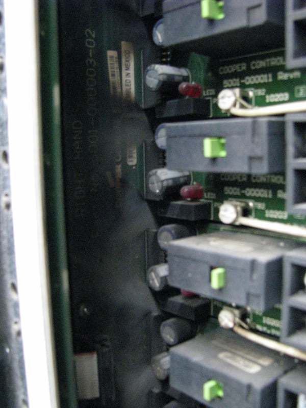
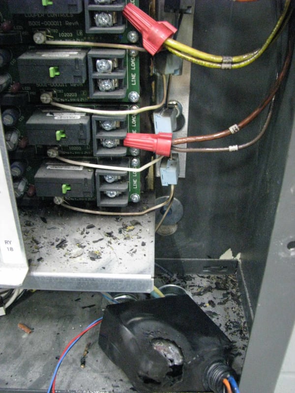
That is exactly what high energy arc destruction looks like with respect to printed circuit wiring boards. Same color I see, same soot patterns. It's what happens when a line-to-line not-bolted arc occurs. It's a dread arc-blast that interestingly tends to blow much larger upstream breakers frequently.

I recently had this happen at a job where a VFD braking resistor was bolted-shorted which connected the VFD's DC bus to ground. The short connected the VFD's rectifier bank from the supply directly to earth which essentially tied all three phases together thru the rectifiers. The VFD rectifier bank completely exploded in a ball of fire that sounded like a grenade going off and it didn't trip the 30A three phase breaking in my hand but did trip the 400A breaker to the building. Similar to your experience with exactly that same soot everywhere.

I believe what's happening in your case is line spikes are violating your lighting gear's voltage rating likely damaging a component, probably a capacitor, and that's resulting in a line to line or line to earth fault. That fault is causing a very high energy arc that's obliterating everything in its vicinity.

You need some form of spike protection ahead of your 'tender' lighting system.

You should also do a survey of your facility looking for anything that could be generating voltage spikes. Things like star-delta motor starters, welders, any large inductive loads. Perhaps large motors. Electromagnets? Large banks of ballasted lamps?

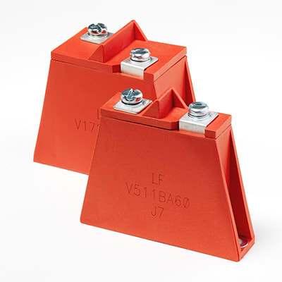
For suppression I'd consider possibly placing a reactor directly in front of this panel and then further placing a power MOV bank between the reactor and the lighting panel. The reactor will protect the MOVs that will protect the panel.

A last possibility is this panel overheating for some reason. Heat causes RAPID capacitor failure and capacitor failures can make this mess.

So;
Survey for spike causing apparatus in your facility. If you find any, deal with them at the location of the problem.

prophylactically add protection in front of your lighting panel.

Keith Cress
kcress -
 
Thank you - I think the culprit is the power pack (switch pack) in the lower right corner of the photo.
That seems to have overheated and created a ground fault which "somehow" blew up the LCP, maybe the fault rating of the switches in the LCP are not rated for that amount of fault current.
Also there are a ton of LED light fixtures fed from multiple LCP's which are sharing neutrals, this might have created the line to line short like you mentioned after the power pack failed.
Based on your advice I will install a data logger and leave it alone for a week and see what happens. I kind of lost faith on MOVs, there is already plenty of surge protection in the property with their pretty led's shinning.
I would definitely like to find out what occurred before I replace the damaged boards on the LCP.
 
Workable plan that. It definitely looks like whatever that is laying on the enclosure floor, took it in the shorts. It's unclear to me what that was or innards looked like from this view. Looks like a cover only? Ohhh wait! I on second look we're looking not at a hole in a cover at the bottom of the enclosure, but a hole thru the back of that thing, at it's fried circuit board?

All the debris laying around is the fragmented back of that device?

Still it's probably an overvoltage issue. Can you relate that thing laying on the bottom to all the soot blowing out of the main panel? Was that directly from The Box or is that further separate mayhem?

While you're monitoring the facility voltage I'm not sure you'll see what could be causing this as they'd be very fast transients.

The MOVs I'm referring to aren't your Mom's MOVs but rather these things:

Littelfuse_Varistor_BA_BB_Image.jpg_dcdocz.jpg


Which are also in products like this.


Keith Cress
kcress -
 
The LED power supply shorting could have shorted the LCP circuit which then blew out and that created an arc that propagated into the other circuits.

I would suspect you need to use fusing for the protection to keep a fault from damaging the LCP. See if the LCP manual has any information on the protection required for each output relay circuit.

All breakers tripping on a fault is fairly common when there is no co-ordination. People forget that having a number of series breakers with no time delay instantaneous trips means they will all trip on a fault. All breakers will detect the fault current when it flows. I've seen a lot of people setting the trip level higher on the upstream breaker and lower on the downstream breaker, but the lower trip setting on the downstream breaker doesn't limit the fault current to that level to prevent the upstream breaker from tripping.
 
The item on the enclosure floor is the power pack (switch pack) that is usually installed further away connected to a motion sensor by the light fixtures.
Sorry for the confusion, I added the item in the enclosure for the photo.
The debris on the enclosure floor is the insulation paper backing from the LCP that caught on fire.
Cool MOVs, what is the clamping voltage range?

 
I managed to download the LCP (Lighting Control Panel) relay information just before the failure occurred, Eaton Cooper controls tech support says the cause is a voltage surge and cannot provide any other information.
All circuits are protected by 277V, 20A industrial bolt on breakers, any additional technical advice on the cause of failure would be awesome in addition to the posted advice above.

Circuit/Relay #2 had the power/switch pack fault that burnt up before the catastrophic failure.

FAILED RELAYS PHASE 1,2 & 3 SHARING NEUTRAL:
Circuit #2 - Relay #2: 291V, 15.7A, 1773W, 59HZ, 0.38PF (Bypassed LCP Amp: 13.2A)
Circuit #4 - Relay #4: 293V, 15.6A, 3961W, 59HZ, 0.86PF (Bypassed LCP Amp: 13.5A)
Circuit #6 - Relay #6: 293V, 26.1A, 7971W, 59HZ, 1.0PF (Bypassed LCP Amp: 13.6A)

FAILED RELAYS PHASE 1,2 & 3 SHARING NEUTRAL:
Circuit #8 - Relay #8: 213V, 22.8A, 6994W, 59HZ, 1.0PF (Bypassed LCP Amp: 13.7A)
Circuit #10 - Relay #10: 151V, 19.8A, 5837W, 59HZ, 1.0PF (Bypassed LCP Amp: 11.5A)
Circuit #12 - Relay #12: 284V, 18.8A, 3329W, 59HZ, 0.62PF (Bypassed LCP Amp: 13.5A)

For some reason I cannot download the weekly data logger information that I set up in the electrical panel, so will have to do it again, =(.
 
Hypothesis - the initial fault caused the neutral conductor / PCB trace to go open circuit somewhere near the power intake to that switch rack. The neutral voltage then was free to float at whatever voltage the loads determined, causing over-voltage failure of loads connected the more lightly-loaded phase(s). As loads fail open-circuit the lightly-loaded phase can change, so it's possible wipe out pretty much everything connected given time.

Around the time I started working at my present employer a loose neutral fault occurred on a huge floodlighting installation, a lot of damage resulted. It's a suspected cause of the tragic fire at the Grenfell tower in London a couple of years ago too.
 
Thanks ScottyUK, I reviewed the information on the tragic Grenfell tower fire.
It seems to have started from a bad neutral connection on the back of a refrigerator.
The refrigerator had plastic backing which burned and ultimately resulted in the exterior flammable cladding catching on fire. Why IEC is okay with so much plastic on their electrical appliances vs NEMA in the US is a whole different subject, but I feel IEC standards are slowly creeping into the US as they are cheaper to manufacture. As long as the grounding and bonding are done right I feel the NEMA standards are superior on mitigating fires.

This provides more respect on my part for metal enclosures specifically where different voltages connect up, I am now thinking of installing the large amount of plastic power packs into metal enclosures so if there are any more failures they are enclosed in metal.
 
Status
Not open for further replies.
Back
Top