Eng-Tips is the largest engineering community on the Internet

Intelligent Work Forums for Engineering Professionals

Pre-Eng Metal Building Roof Addition 1

Status
Not open for further replies.

matty54

Industrial
Feb 10, 2022
65
0
0
CA
Hi there,
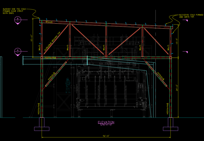
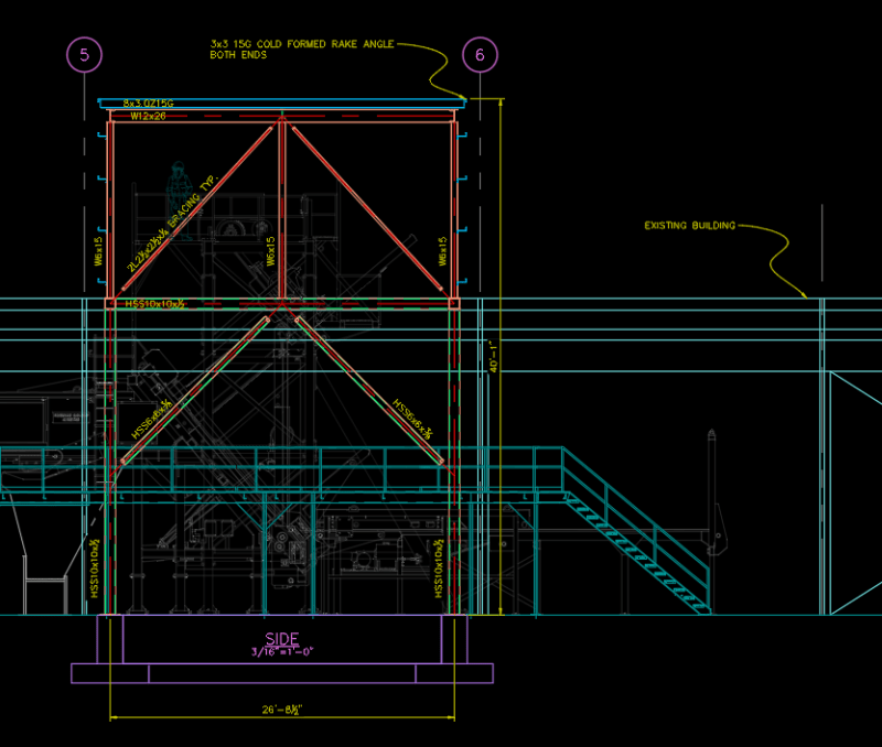
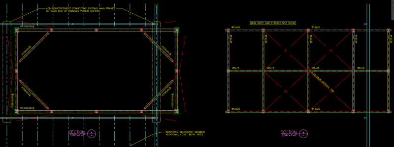
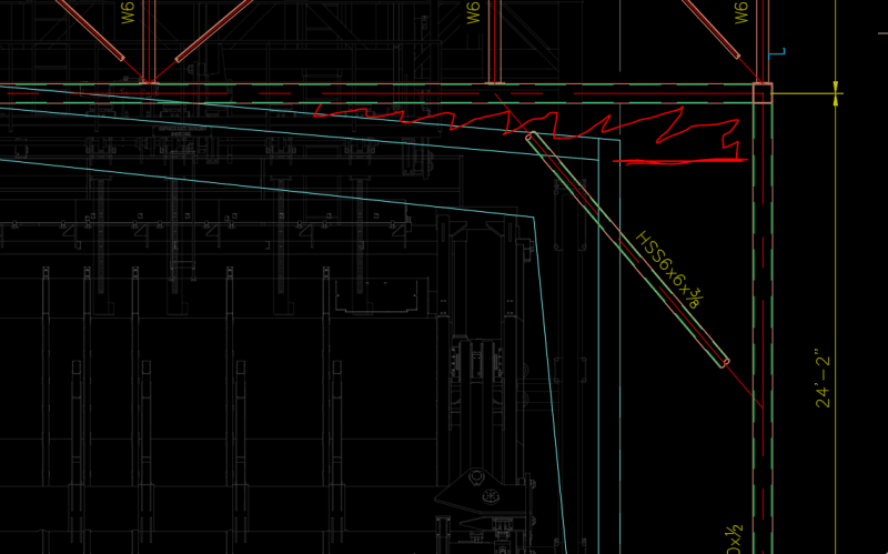
I have a project where machinery is being installed inside an existing pre-eng metal building. One of the machines is too tall and is going to be sticking out through the roof so they are wanting a doghouse structure built on top of the roof to cover and enclose it (approx 30'X40'X 15'). I've told those in charge that additional columns would need to be added under the PEMB frame and that there would need to be quite a fair amount of analysis involved since there will be no extra strength from the PEMB that we can use. The issue that I have come across is that the client has no drawings of the existing PEMB or its foundation. So I'm trying to figure out what the best course of action would be other than trying to excavate to see foundation sizes or measuring up every piece of the PEMB. Has anyone been in a similar situation? I thought maybe I would request that the client reach out to the PEMB manufacturer and ask for more drawings? Other than that, maybe the only other option would be to build this structure completely separated from the PEMB with new columns running between the frames. Thought?
 
Replies continue below

Recommended for you

Cutting out the roof panels, I assume also means cutting out the purlins, these purlins may be providing bracing to the main girders. Additionally, the load path typically uses the purlins to distribute loading between the girders and then the braced diaphragm, so cutting them out means you may need an alternate load path for the PEMB. I doubt you will be able to get any PEMB drawings and if you did, they may not give you what you want. I believe you may have to start measuring everything and analyze the full building in RISA or another software, but I caution that you may not get desirable results. Because I have never gotten a PEMB member to actually calc at less than 103% utilization, I suggest running the building as is and then comparing the model with the cutout to see if any utilizations actually changed utilizing the International Existing Building Code as a guide for allowable stress increases.

Edit: Just noticed your are in Canada, however I suspect Canada also has existing building codes.
 
I would definitely do an independent structure up through the roof. You're unlikely to get any information on the PEMB itself, and even if you did, it's extremely unlikely to work for the additional load from the doghouse above. Assuming you're in an area with any kind of snow load, you'll be adding drift to the PEMB structure. You'll need to go measure the frames for that regardless, as well as any cold-formed purlins that are cut, since they'll lose continuity.


Go Bucks!
 
Yes, the purlins will need to be cut so that the continuous span will be turning into a simple connection on the one side. I was planning of having to add more purlins onto these adjacent bays for this reason. Just looking at the size of the doghouse it will probably be 30-40 kips additional load all together so ya I think even if I had the drawings to analyze it I would not end up getting the result I was looking for. Separate structure it is! Mind you I will still have to account for a rather large section of purlins being cut out. Anything else for the existing PEMB that I should look out for other than additional drift?

Aesur: Yes I am in Canada, but this job I am doing is in the states in Arkansas. I am doing all the prelim design and engineering and we are going to get a US firm to re-check and stamp for us.

 
PEMBs often use the purlins as struts to take the endwall wind to the horizontal roof trusses. If you're taking out some that align with endwall columns, you'll need to devise a way to get the load around the doghouse, or make sure the trusses (and the foundations) are sufficient for the extra wind load.

As Aesur pointed out, the purlins were used to brace the top flange, and there are likely fly braces to brace the bottom. If you're only removing one bay of purlins (between two lines of frames), it's less of an issue since you can brace back out to the other side. If you're taking out more than one bay (i.e. both sides of a single frame line), you'll need to come up with a way to properly brace the rafters.

Go Bucks!
 
It's sometimes difficult in confirming the strength of PEMBs for the original design loads; they are very tightly designed. Alterations can be particularly challenging, in particular to added loads, equipment, snow, snow accumulation. Any mods and you 'own' the new design. Just a caution.

-----*****-----
So strange to see the singularity approaching while the entire planet is rapidly turning into a hellscape. -John Coates

-Dik
 
I've done a few of these in the last couple years. I typically go independent for the new structure, then reinforce the existing adjacent members for snow drift. It can be easier to add supplemental frame lines between existing bays, to cut the purlins spans down instead of reinforcing everything.

Since the clients may not be able to accommodate braced frames at the operating floor, the new structures tend to be moment frames, or a combination of moment frames with braced frames above.
 
It's kind of situation/location dependent. On my most recent project, the PEMB was from the 1950's and had a unique lateral system in the long direction, with roof trusses and continuous rods running full length of the building at the bottom chords. My new high bay was at the end bay of the building, so I just re-terminated the rods at the adjacent bay and the load path was essentially unchanged. On another project, the new high bay was between X-braced roof bays, so again the lateral load path wasn't really affected.

I did another one that I called an "elephant in a shoe box" building, where the new high roof was taking up about 2/3 the footprint of the existing building. For that one, I connected the old and new structures and designed the new bracing for the entire building.
 
This is a sketch of the direction I am thinking of going with this. (note sizes are not confirmed). Basically planning on building a really skookum HSS frame and then sitting the enclosure on top.
elevation_tzvvvh.png


side_vuony5.png


sections_tmwojc.png


bones206 said:
I've done a few of these in the last couple years. I typically go independent for the new structure, then reinforce the existing adjacent members for snow drift.
bones206, was there anything special needed to adjoin the metal roofing in this case to ensure there was no leaking or that there could be relative movement between the two? There is one area here where there is going to be a bunch of irregularly shaped spaces that I am going to have to figure out how to fill in somehow also going to try and have a brace coming through the existing wall:

fill_tv5jyl.png


bones206 said:
I did another one that I called an "elephant in a shoe box" building, where the new high roof was taking up about 2/3 the footprint of the existing building. For that one, I connected the old and new structures and designed the new bracing for the entire building.

I thought this might be an option here for me to run the cut purlins on each end into my new structure
 
I may suggest simplifying the longitudinal section by doing a clear span moment frame rather than a braced frame/truss. It should have similar stiffness to somewhat match the drift of the original PEMB frames. I usually let the architect worry about flashing and roofing tie-ins, but it's a good idea to calculate upper bounds and let the architect know what they should accommodate.

For the roof diaphragm, I like to use rod X-bracing. Just because it's simple and cheap, with easy connections.

I don't necessarily see a need to connect the existing purlins to your new structure. You may need a sloped bottom girt just above the existing roof to attach the bottom of the new roof panels.
 
bones206 said:
I may suggest simplifying the longitudinal section by doing a clear span moment frame rather than a braced frame/truss

Unfortunately, I don't have much room outside the PEMB for the foundation pad (there is another storage structure outside beside this PEMB) so I will have to use the braced frame in order to cut down the moment in the foundation so I can reduce the pad size.
 
unless I can design HSS foundation connection as pinned. But I'm not quite sure how to do that with HSS baseplate having anchor bolts on the outside. Not sure I want to go into that design challenge figuring out exactly how much moment I can get reduced from using a thinner baseplate.
 
This is my approach for what it's worth:

1) Design column base as pinned for frame and foundation design
2) Design column base as fixed for anchorage design.
3) Apply a rotational spring at the base for frame drift calcs.

You could also consider wide flange columns, and putting anchors between the flanges as is typically done for PEMB's.

Nothing wrong with your proposed design, I just mentioned the moment frame as a possibility. The truss just looks a little on the expensive side and maybe more difficult to construct. Usually one of the constraints on this type of project is minimizing construction duration with the existing roof taken off. So any structural system that can be erected quickly to get the building re-covered is advantageous.
 
Status
Not open for further replies.
Back
Top