Eng-Tips is the largest engineering community on the Internet

Intelligent Work Forums for Engineering Professionals

Precast flat slabs -> tying together for higher diaphragm capacity?

Status
Not open for further replies.

Backcheckrage

Structural
Sep 23, 2012
84
0
0
NZ
Hello fellow nerds,
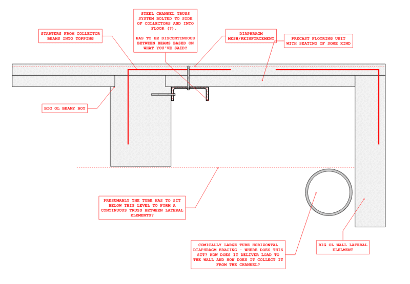
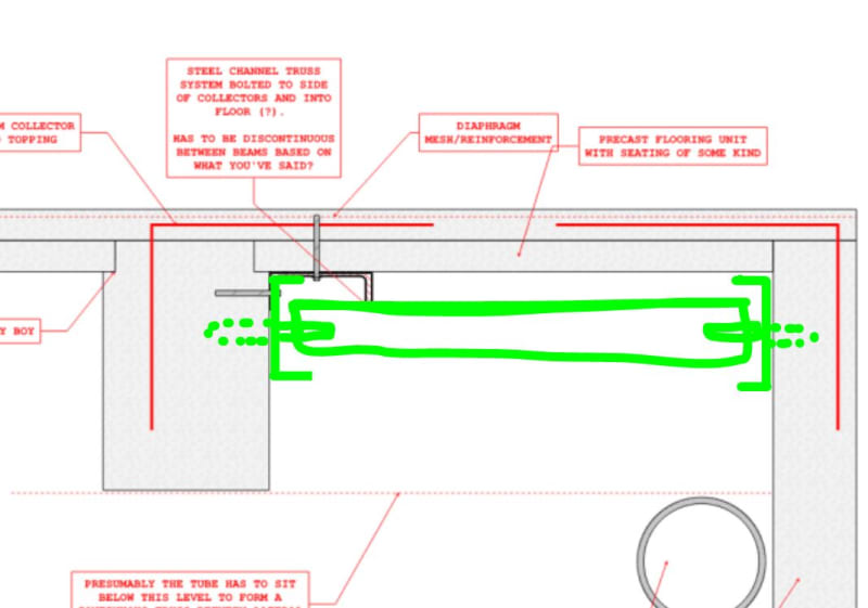
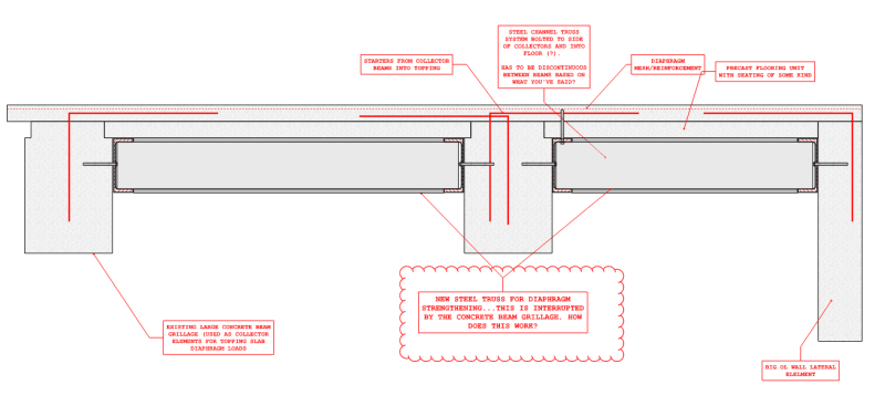
I am exploring the idea of stitching together precast floor panels so I can unilise the entire depth of the floor (75topping+75unispan).
Is this a hair brained idea?
The top of unispan is indeed roughened so I believe it will act with the topping (just not at the abutting panel joint, hence why proposed steel plates).

Has this been done before? I cant find any photos or literature on the google.
 
Replies continue below

Recommended for you

What efficiency are you actually trying to get - your title says diaphragm so I'm thinking lateral load transfer in some way...?

My initial response:

Yea I think it's a bit hairbrained.
There's not really any tie between them - the interface may be roughened but that only gives you a bit of tension in the concrete bond
As soon as that fails (probably pretty quickly) you'd be stuck with two separate pieces of concrete and a diaphragm that doesn't match your design assumptions
If you have a system with lots of coil connecting the two you could look at it as you'd be ab
le to numerically quantify your bond across the interface

Then I remembered that there is some guidance in the C5 seismic assessment yellow book (go to page 189)
This recommends using the combined thickness of the topping & units when modelling diaphragms with in-situ/flat slab precast units
I don't know if this is exactly what you're looking for?

 
Thanks Green,

I am interested in the in-plane diaphragm shear capacity of a transfer diaphragm above a basement. There's apartment mass uptop that wants to have it's shear forces transferred to the basement shearwalls below which are offset from the bracing system of said apartments.
The original drawings have just 75mm over 75 unispan... and is blowing up in terms of shear per meter capacity as I considered only the 75mm topping as effectice (Vc of topping).
I have come up with a trussed diaphragm strengthening solution but it looks really gnarly.
I have dreamt up a detail of tying together the unispan flatslabs at their abutting edges with steel plates but that blows up too I just ran a profis on it.

So I think I am stuck with a steel truss diaphragm within the beam grillage to get some strength and stiffness. I would consider FRP but that blows up too.

Appreciate your thoughts!
 
I don't think that will work?
Your flooring will only have strands in one direction and you won't be able to anchor them at the perimeter so your critical shear plane won't change - it will still be in the topping
75mm seems too fine anyway, you won't fit all your steel in and buckling of the topping slab is a risk from the compression strut in the diaphragm shear
 
Green

The 75mm topping slab has starters down to grillage of cast in place concrete beams (something like a 5.5-6m grid of them). I am inserting a steel truss diaphragm between said grillage with channel steel all around epoxied into said precast. The steel braces are connected via gusset plate brackets dragging load to said channel trimmers withing the grillage.

The design disregards the capacity if the existing 75mm topping. It is very very poor given the demand transfer shears from the above masses.

So I am imagining the topping isn't there, and the new steel X's within the beam grillage will offer the stiffness/strength.
 
Sorry, poorly worded on my end.
I meant that I don't think considering both the topping and the unispan working as a diaphragm together will work for the reasons I outlined
Surprised that FRP didn't work...and if FRP didn't work, will you really be able to get a steel truss diaphragm to work? I would think getting your nodes to work will cause huge forces on the bolts?
 
Correction on my part - FRP calcs out with with pretty intense grillage of it but it would require evacuating the tenants above because it's a topside application.

I didn't do the truss method for diaphragm analysis, rather just semi rigid plate analysis within ETABS. The connections do take a boat load of force, M24 bolts. Big tube cross members too.
 
Can you really get enough load out of a 75mm topping slab and into your steel members, even with M24 bolts?
That's a very thin slab and you're likely to blow the bottom out when you drill, even with the unispan below - you may not achieve the capacity you expect
Is the purpose of this steel to replace the entire diaphragm or just to help you upgrade the connections?
You have to think carefully about the load path on this one - if it's to replace your diaphragm entirely then you'll need to connect to all the lateral elements more so than the slab itself
Do you have any sketches of the proposed installation/existing building?
 
I think there's nuance here which is hard to convey in text (I dont really want to do broadcast sketches on this one).
But yes, there's enough shear friction from the starters in the topping to get load into the concrete beam grillage. Once the load is in a beam line (collector line) , I can transfer it with steel elements across the bay to shearwalls and unload it there. The PFC trimmers act as drags for the brace connections via site welded plated. PFC trimmers are all epoxy bolted to hell to the concrete beams grillage.
 
Ok that makes some sense - your plan is to collect inertial loads at each level within subdiaphragms (slab into existing concrete beam) then take it into a steel truss and from there into the shearwalls and down to ground?
Is your building regular? Do you have to consider transfer forces within the diaphragms at each level?
 
Green
- it is indeed a regularly building.
-transfer forces are at worst on podium level, where the bracing lines for the apartments above do not extend below.

 
Alrighty. What's your plan at the podium level then? Presumably that's your critical level for diaphragm action?
Something to consider with your proposed steel truss is the relative stiffness of your diaphragm vs steel
You need your steel to be REALLY stiff to make sure it takes load from the diaphragm
Bolt slip will be an important consideration here that a typical static analysis won't consider

I assume your new steel truss diaphragm is going underneath the existing floor slabs as otherwise walking will get a bit difficult..
In that case, what is your plan for the vertical eccentricity between the shear force in the topping slab and the resistance at underside of concrete bema level?
 
Yes, i looked at diaphragm compatibility. The steel truss diaphragm strengthening indeed has to be the biggest tube you can get just to see the loads. I had to assume the 75mm topping was ineffective (eg a small inplane stiffness modifier) in order for the truss to participate as a diaphragm.

the existing beam grillage is huge, like 500-700 deep beams. And the truss is only held down 30mm or so from underside of slab. I am not worried about eccentricities in this detailing.
 
How does that placement work? Presumably if your truss is at the underside of the slab then it is discontinuous at the beam locations?
Agreed that I would ignore the eccentricity if it was only 30mm or so though
 
Green-
the load transfer originates from the bracing elements above the basement -> into the conc big beam line as a collector -> unloads to PFC channels which are epoxied to heck to said all conc collector beamline (all the bays are trimmed with PFCs in this zone) -> gussets from field installed PFCS with site welded splice plates to said collectors) -> gussets to comically large tube horizontal diaphragm bracing
 
See my sketch below - how does this all work?
Screenshot_2024-04-03_145953_lsv8qp.png
 
there's details like the slab on left side of beam is very thick with real reinforcing... it steps down to the very shallow topping with poo poo mesh.
But the new strengthening bits are in green.

Capture_orouk7.jpg
 
The trusses run down the entire length of building (into the page of your sketch).
In-plane diaphragm shear transfer through the diagonals.
The associated T/C resolved in the big beams.
think of a long braced frame elevation but tipped over on it's side...
 
Status
Not open for further replies.
Back
Top