For precast panel to panel with dowel bars vertically how do u check the shear capacity? Do you still use the concrete shear capacity from the wall fc or the grout one or you don’t use concrete shear capacity at all but purely reply on the dowel bar shear capacity ?
Navigation
Install the app
How to install the app on iOS
Follow along with the video below to see how to install our site as a web app on your home screen.
Note: This feature may not be available in some browsers.
More options
Style variation
-
Congratulations MintJulep on being selected by the Eng-Tips community for having the most helpful posts in the forums last week. Way to Go!
You are using an out of date browser. It may not display this or other websites correctly.
You should upgrade or use an alternative browser.
You should upgrade or use an alternative browser.
Precast panel shear capacity at connection 1
- Thread starter Gile_
- Start date
- Status
- Not open for further replies.
Are you describing the connection between two wall panels stacked vertically?
Is your primary concern in plane shear or out of plane shear?
A sketch showing your situation with some forces etc will likely go a long way towards the quality of the answers that you receive here.
Is your primary concern in plane shear or out of plane shear?
A sketch showing your situation with some forces etc will likely go a long way towards the quality of the answers that you receive here.
- Thread starter
- #3
Sorry for my wording.
It’s in plane shear to lateral loads.
Panels connect vertically using grout and dowel bars. I was just wondering how to check whether dowel bars are adequate in this case. I have seen come engineers treating dowel bars like normal rebar in concrete section and getting the shear strength from concrete Vu plus dowels bars Vs while some other engineers use the dowel bars capacity Vs only and not including concrete one Vu. Which one is correct?
Use shear friction at joint for shear, and for flexure analyse wall section with the dowel reinforcement to model the flexural capacity of the dowels at the joint.
1) I don't think that it would be valid in most situations to assume that the steel shear capacity of the dowels themselves represents the governing shear capacity of the connection. It's usually a concrete failure mode that governs.
2) If you've got a number of dowels spread out along the joint then shear friction is a commonly accepted approach. I personally worry that, under significant flexural strain, shear friction doesn't work as well as we think it does but that's just a me thing. Others don't seem to be bothered by this so I mostly don't let it bother me either.
3) If you only have dowels at the ends of the panels, I probably wouldn't use shear friction for that and would be inclined to use something more like fastener anchorage provisions, acknowledging the potential for concrete breakout.
4) North American codes don't really have provisions for true shear dowels. I know that some other jurisdictions do however. Where that's the case, and where those provisions would consider concrete stresses, I'd certainly be willing to make use of those techniques in place of shear friction.
Gile:
Don’t many precasters just cast weld plates or angles into the edges of the panels at regular height intervals and then just weld a light steel bar over the joint at each set of weld pls? Then, of course, the shear strength is a function of the welds and those bars, and their embedment in the edge of the panel.
Don’t many precasters just cast weld plates or angles into the edges of the panels at regular height intervals and then just weld a light steel bar over the joint at each set of weld pls? Then, of course, the shear strength is a function of the welds and those bars, and their embedment in the edge of the panel.
@dhengr: I certainly do that on vertical joints between side by side panels. My understanding here is that OP's talking about vertically stacked panels. In that situation, I've been avoiding the weld plates on the horizontal joints because it's difficult to prevent them from attracting the vertical load in the system in addition to the shear. Perhaps that's just paranoia on my part, I'm not sure. Dowel in the horizontal joints also seems to appeal to precasters for erection convenience.
Kootk, if the dowels are fully developed either side of the joint as is usually the case (round here at least it is the requirement) then isn't shear friction the obvious choice. What other limit states are you proposing to check with respect to your concrete based failure?
It's the difference between rebar and anchor theory, not full development = anchor theory/concrete failure possibilities, but miraculously provide enough development (and appropriate detailing/load path) and suddenly all your concrete mechanisms vanish.... magic...
It's the difference between rebar and anchor theory, not full development = anchor theory/concrete failure possibilities, but miraculously provide enough development (and appropriate detailing/load path) and suddenly all your concrete mechanisms vanish.... magic...
Agent said:Kootk, if the dowels are fully developed either side of the joint as is usually the case (round here at least it is the requirement) then isn't shear friction the obvious choice.
Yes, shear friction is certainly the conventional choice and I do it myself for lack of better options. All that follows should be put into the classic "KootK Overthinking Bin".
Agent said:What other limit states are you proposing to check with respect to your concrete based failure?
One of the cases of concern that I mentioned is that of only anchors at the ends of the panels as shown in the first sketch below. Hopefully the sketch makes the concern self evident. It's a bit more common of a case than one might think because many shear friction recommendations are predicated on flexure shifting the location of shear transfer to the compression zone.
The other point of concern that I mentioned is shown in the second sketch below and it results from the test setups used to evaluate shear friction capability not having meaningful flexure present.
Agent666 said:It's the difference between rebar and anchor theory, not full development = anchor theory/concrete failure possibilities, but miraculously provide enough development (and appropriate detailing/load path) and suddenly all your concrete mechanisms vanish.... magic...
I'm familiar with that popular distinction but consider it something of an oversimplification. At the end of day, stresses are stresses, failure mechanisms are failure mechanism, and a thing feels what it feels under load. Having put a particular situation into a convenient taxonomic bucket changes none of that of course. In my opinion, many cold joints will start to slip into something of a grey zone between rebar theory and anchor theory.
Nobody should believe in magic. There are always nuances and costs to things.
The easy rebuttal to my hypotheses here is "properly designed flexural elements don't open up enough to create those issues". But, then, can that be proven to be true?
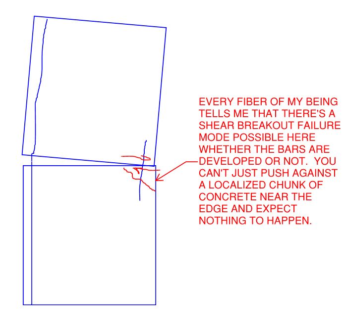
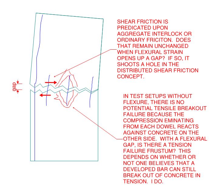
So does the NZ concrete code include shear friction? As far as I know, the Australian code does not.
Yeah of course it does, we have traditionally been 20-30 ahead of your codes being historically based on ACI318 approaches.... the stuff you've just had added to your code in the last few years regarding capacity design for example has been in our codes in one form or another since the early 1970's as a fair dinkum extreme example of how far behind you cobbers have been
![[bigsmile] [bigsmile] [bigsmile]](/data/assets/smilies/bigsmile.gif) .
. Kootk, in my mind dowels just at the end would not comply with the minimum reinforcement requirements for your wall. The dowels still need to comply in my mind as far as practical with all the wall provisions, spacing, min/max area, etc. They are part of the wall. So, I agree if you're lumping 2 bars at the end of the wall and hoping to rely on shear friction then I think you're on your own there and something unexpected may occur in line with what you've proposed.
You'd be concentrating the shear significantly at the bars at end of wall which is not the more or less distributed shear stress model we assuming in your typical reinforced concrete shear design. Do a strut/tie design in this case and consider appropriate concrete breakout like you say, or better yet just don't do that ever....
In my mind I've always developed the dowels, but also demonstrated that they lap with the wall reinforcement both sides of the joint which often requires a much longer lap than minimum code requirement, effectively discounting the possibility of a chunk of concrete tearing out like shown in your second sketch. Simplistically you could apply the offset lap provisions, or alternatively demonstrate a strut/tie solution if you had weird layout of wall or dowel reinforcement and you were trying to lap a single dowel at wider spacing with multiple bars along the wall at closer centres for example.
Agent666,
I thought as much, but we have different opinions on the matter. The shear-friction theory has never made sense to me, and still does not. KootK and I have debated this at length, but some time ago, and I will just leave it at that. But his illustrations above illustrate some of my misgivings. Shear-friction depends on a clamping force, yet some folks will count bars in the compression area in their calculations.
I thought as much, but we have different opinions on the matter. The shear-friction theory has never made sense to me, and still does not. KootK and I have debated this at length, but some time ago, and I will just leave it at that. But his illustrations above illustrate some of my misgivings. Shear-friction depends on a clamping force, yet some folks will count bars in the compression area in their calculations.
- Thread starter
- #13
Thanks for everyone’s insights.
Agent666. Do you mean dowel bars + shear friction = shear strength?
I am looking at ACI chapter 17 - anchoring to concrete but cannot find the shear friction. Do you mind if you can provide me an example if possible.
I am also very interested in the difference between rebar theory and anchor theory. Do you have any source that you can share on this topic?
In regards to concrete break out at the edge, won’t the horizontal reinforcement in the panel provide some resistance as well?
-
1
- #14
Gile_ said:In regards to concrete break out at the edge, won’t the horizontal reinforcement in the panel provide some resistance as well?
Indeed it will, as with most anchorage problems/methods. The question then becomes how much rebar is engaged and how is the rotational stability of the piece that would break off ensured. In the generalist of terms, the trouble becomes that you're forcing all of the panel shear through a localized area at the end rather than in a distributed fashion so your "shear depth" kind of becomes the width of the breakout frustum rather than the width of the wall.
Gile said:I am also very interested in the difference between rebar theory and anchor theory.
The difference is basically this:
1) In rebar theory (reinforced concrete theory) all primary tension is passed to reinforcing bars and between reinforcing bars. You never rely on concrete's tensile capacity other than for incidental stuff like cover splitting etc.
2) In anchor theory, you are very much relying on concrete tensile capacity in the primary load path. The various forms of concrete breakout are really limited by concrete tensile capacity around their perimeters.
Giles said:I am looking at ACI chapter 17 - anchoring to concrete but cannot find the shear friction.
A healthy chunk of the 318-14 shear friction is shown below.
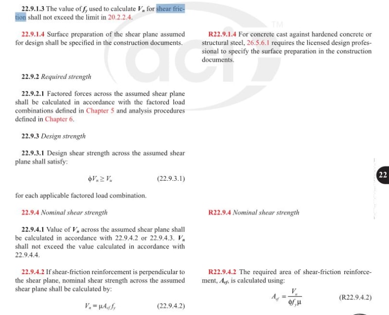
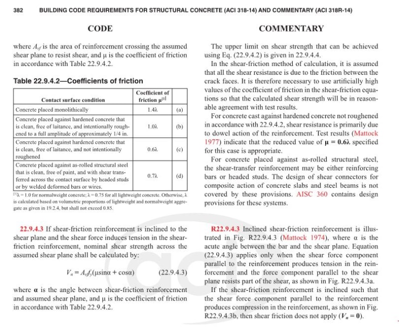
Agent66 said:The dowels still need to comply in my mind as far as practical with all the wall provisions, spacing, min/max area, etc. They are part of the wall.
I agree that would change the picture for the better but are you really able to get that kind of interconnection between vertically stacked walls in NZ? Over here, we'll have just enough connection between walls so as to not run afoul of equilibrium and that's it.
.Agent666 said:...but also demonstrated that they lap with the wall reinforcement both sides of the joint which often requires a much longer lap than minimum code requirement
I agree with that too and think it a fine practice. It's also pretty easy to accomplish in a typical CIP wall where your bars are pretty close together and you're allowed to offset 6" before your into offset splice territory anyhow. I do wish that codes would speak directly to this practice though. The use case that initially got my hackles up about this was reading about seismic retrofits where frames are infilled with wall panels as shown below. No laps unless it's indirectly through beam stirrups I suppose.
Agent666 said:...which is not the more or less distributed shear stress model we assuming in your typical reinforced concrete shear design.
This I get mixed messages about in the literature. Consider:
1) With shear friction you will often see recommendations about putting the reinforcement in the tension zone in acknowledgement that most of the action happens in the compression zone. Not distributed.
2) In any flexural concrete member, I would argue that we don't actually assume a linear distribution of shear resistance and that, rather, the lion's share happens over the compressed zone. The cold joint example is quite similar to a pure flexural crack where there really is little to resist shear other than the flexural compression zone. And this leads to an important feature lacking in the shear breakout mechanism of the first sketch that I posted here. That frustum at the end of the wall, presumably, also has a ton of compression applied to it which would surely improve it's shear resistance. In this respect, perhaps the joint becomes little different than the shear resistance mechanism at any, predominantly, flexural crack.
All of these things reinforce my feeling that some testing should be done on shear friction in the presence of significant flexure. The test setups that I've see in the literature for shear friction all simulate about as close to a pure shear situation as one could imagine. But many shear friction situations in the wild are accompanied by significant bending as well.
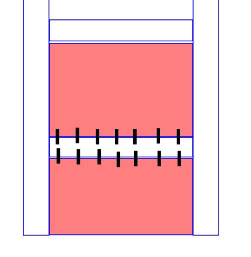
hokie666 said:KootK and I have debated this at length, but some time ago, and I will just leave it at that.
Ah yes... my early thirties spent productively (seriously). And the reason that a lot of my details retain shear keys of various kinds to this day. The KootK needle on shear friction has actually swung somewhat your way a fair bit over time.
hokie66 said:Shear-friction depends on a clamping force, yet some folks will count bars in the compression area in their calculations.
Right. Not only might the compression zone bars not help with shear friction, one might also suppose that they detract from it by shielding the concrete from some of the compression induced there by flexure and the the tension zone bars. I see this as being somewhat validated by the blurb below on inclined shear friction bars. What is one to do in the case of a conventional shear wall though? The tension bars for one direction of loading usually become compression bars for the other...
Again, I'm not saying that I feel shear friction is bad and should be scrapped wholesale or anything like that. I just feel that the research underpinning it lacks similitude with real world applications. And if the history of our profession has taught us anything, it should be that whenever we extrapolate too much from simplified testing we wind up getting burned, either a little or a lot. Back to the whole "no free lunch" thing...

Kootk, this thread shows the ideal/recommended arrangement in NZ following our experiences learnt in our 2011 earthquakes.
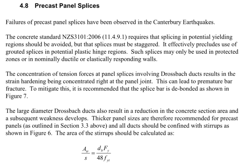
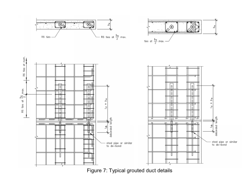
The issue we had was while the strength of isolated bars was fine on paper for equilibrium, we had bars at ends of walls fracturing under cyclic loads due to the very low reinforcement ratio. Strain too high basically and suffer low cycle fatigue failure concentrating all the inelastic strain in a very short portion of the bar.
Put more bars in wall ends (like equivalent reinforcement to the wall vertical steel) and you reduce this possibility. ACI code directly adopted the exact same learnings by increasing minimum reinforcement content in wall ends that we introduced. Doubling the previous requirement from memory.
Any connections between wall panels should follow the same principles regarding reinforcement ratio. It's possibly the worst thing to do just satisfying equilibrium with a few isolated bars at wall ends as per your example.
Agent666 said:Strain too high basically and suffer low cycle fatigue failure concentrating all the inelastic strain in a very short portion of the bar.
Just as one would expect with any under reinforced beam. The details look slick, much less onerous than I might have imagined.
Agent, I was reading the study below recently, and see this is a common detail. Can I ask if it is common to connect panels in a similar manner at the vertical joint lines or do most EOR's design the foundations for the forces without panel to panel connections? Any chance you can point to a NZ study showing a nice method to determine the panel/panel forces? We use FEA methods, but I have never been completely satisfied with that.
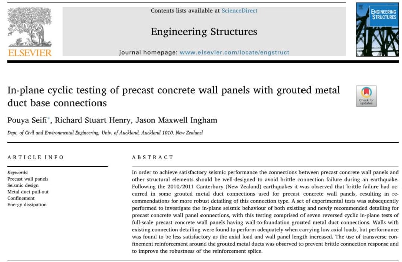
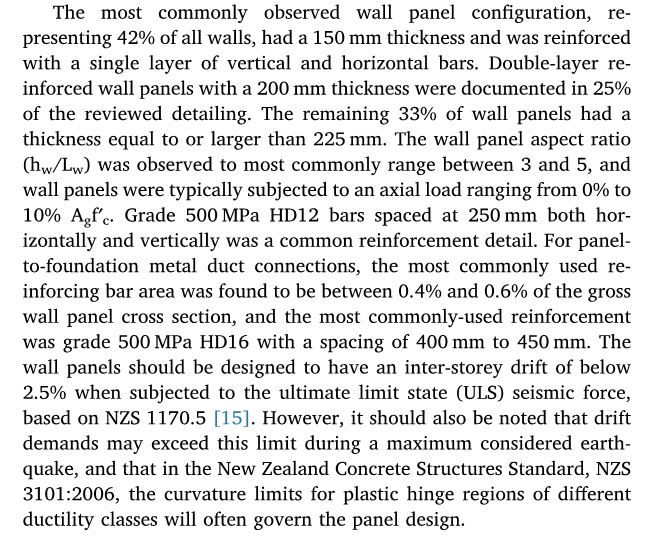


Brad, really depends on building and whether you need the longer wall as to whether they are jointed.
This document is a bit old but it gives a flavour for how walls might be joint in NZ. Refer to section 4. Some of the more elaborate ones I've never seen in practice, but the half thickness joints or full thickness seem to be the most common.
In terms of evaluating the forces crossing the vertical joint, isn't it just a matter of evaluating the wall bar and compression forces and evaluating the longitudinal shear (when the wall is at its ultimate strength/capacity). In squat walls strut and tie could help. Even a section cut on etabs is probably sufficient if your wall is elastic.
- Status
- Not open for further replies.
Similar threads
- Question
- Replies
- 2
- Views
- 8K
- Replies
- 1
- Views
- 2K
- Replies
- 22
- Views
- 6K
- Locked
- Question
- Replies
- 0
- Views
- 818
- Replies
- 2
- Views
- 5K
