Continue to Site

Eng-Tips is the largest engineering community on the Internet

Intelligent Work Forums for Engineering Professionals

  • Congratulations KootK on being selected by the Eng-Tips community for having the most helpful posts in the forums last week. Way to Go!

Preload Gap (Back-to-back Configuration) 2

Status
Not open for further replies.

TheBearingDude

Industrial
Jan 12, 2021
6
Hello,
I've been thinking about the possible meaning of this image:
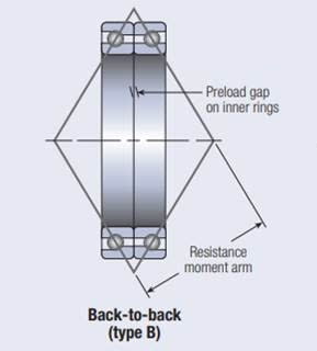
image058_te4bll.jpg

It says "Preload gap on inner rings" and since this could have different meanings I was hoping someone could help me clarify.

Does it mean:
- You need to leave a minimum gap between the bearings (using a spacer placed in between the outer ring) so that when the axial load is applied (the minimum axial load necessary for proper funcioning) both inner rings have enough space and don't touch each other.

- The inner ring is actually slighty thinner and already takes that into account so the outer rings can just directly touch each other and the inner rings won't collide when basic functioning load is applied.

-Something else I am not seeing.

Any imput can be good. If you know the exact answer it would help a great deal.
 
Replies continue below

Recommended for you

Neither. Sitting free on the bench, there would be a tiny gap at the inner races at the point where the outer races were in contact. When the bearings are properly mounted, the inner rings are forced together as the shaft nut is torqued. This puts the bearings into a slight pre-load condition, even with no external load. This would not be recommended for high temperature services. Bearings of this type require a different specification for bearing to shaft fit in order to avoid overloading.

Johnny Pellin
 
Senza_nome_pjmbw9.png


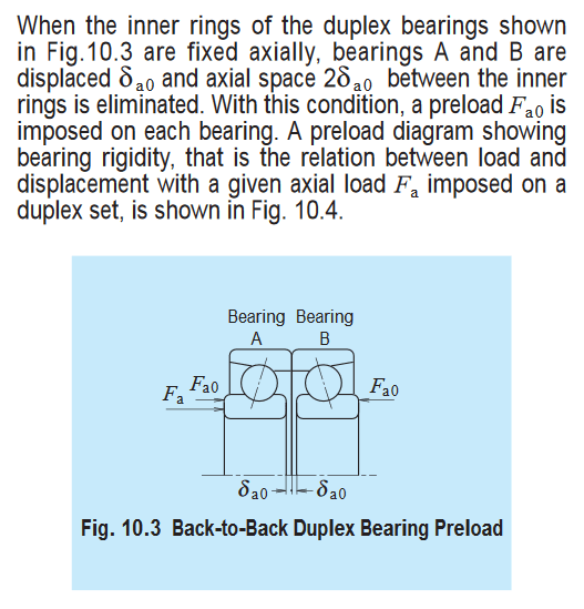
Is that the "gap" you are referring to?
Is δa0 a known value usually listed on the bearing specification? Is it calculated?
 
Yes. That is the gap. I have never seen that gap called out on a spec sheet for a given bearing. If you contact the bearing manufacturer, they may be able to provide it.

Johnny Pellin
 
Hello TheBearingDude,

What are you wishing to accomplish?

"Is δa0 a known value usually listed on the bearing specification? Is it calculated?"

Precision spindle angular contact bearings are often available as pairs in light, medium, or heavy preload.
In the precision spindle bearing catalogs the stiffness and speed rating of the various preloads is listed.
The difference is the built-in face offset = your δa0. The difference between the levels of preload is generally just a few .0001" as mentioned by others.

Many spindle designs include spacers between the inner and out rings of the bearing pairs. This provides the builder or rebuilder the opportunity to turn light preload bearings into heavy preload etc by machining the spacers to slightly different lengths.

For the highest speed capabilty the axial preload is applied by springs, since the flexibility will prevent higher speeds and resulting increased temperature from jacking up the preload, as happens in rigidly mounted bearing arrangements. A rigidly mounted light preload bearing pair can cascade into heavy preload and then RAPIDLY to disaster if the spindle is brought up to full speed too quickly, or other operating conditions cause the system to take the first step toward thermal run-away.

The bearing manufacturers have internal programs to cypher out the proper offset for a particular preload rating when rigidly mounted. I'm guessing Those programs are Probably verified and tweaked by a batch of empirical testing. Top secret bearing details like bearing curvature make the "calculation" of bearing offsets no job for those without those specific programs. There are attendant/equivalent axial spring forces listed to create the different levels of preload.
 
I cannot talk about it in too much detail but we are talking about thin section angular contact bearing to be used in a cycloid reducer.

Knowing more about this "gap" or δa0 is important in order to then calculate the thickness of a couple of spacers.
This so that when the whole reducer is assebled and the main bolts tightened the bearings go into preload and at the same time there is no play left inside amongst other components.

Everything is taken into account in what we call "chain of tolerances calculus" where we add up all the tolerances of the components and the result is supposed to be as close to zero.
The thing is at the present time I'm not sure if we need to take into account the δa0 in this chain of tolerances.
 
If you are buying the bearings with a desired preload, the goal is probably spacers of precisely equal length so the faces of the bearing inner and outer races are co-linear when everything is bolted and clamped. Perhaps it is easier to see if a design without spacers is imagined. The Bearings will be installed with the engineered preload if the inner and outer faces were clamped together, positively closing δa0 .

The actual details of your design should be discussed with Kaydon or whoever the bearing manufacturer is.
This is almost certainly far too important to be guessing.
 
Hah- Kaydon't
This brand was discussed recently but it's way too expensive.

I'll see if I can upload a drawing later today (a pen on napkin kind of drawing, I can't disclose any official technical drawing, even if redacted).

This way you'll understand better the exact configuration and the spacers position.
 
Any input can be good. If you know the exact answer it would help a great deal."

8 posts and I still don't understand what TBD is asking, and especially what needs to accomplish.

Alas.................
 
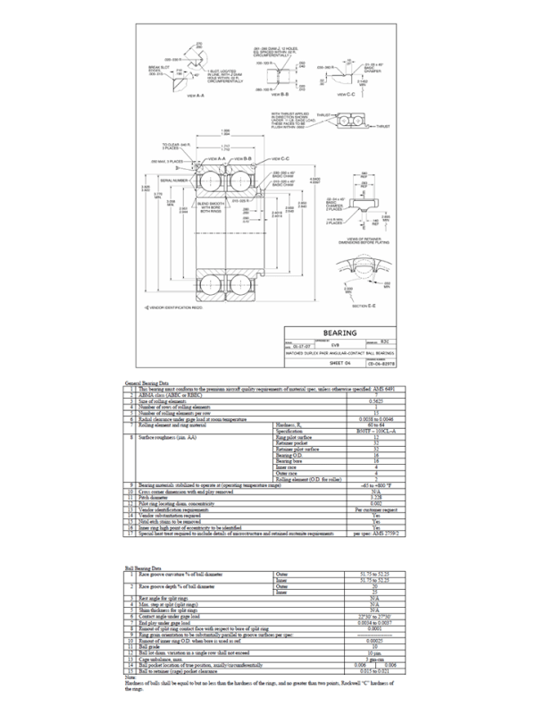
A gauge load is normally specified for inspecting angular contact ball bearing characteristics like preload gaps or contact angles. Gauge loads are usually just enough to produce uniform contact between the ball complement and race surfaces. Modern rolling element bearing analysis software applications are very good at calculating things like gauge load preload gap vs installed preload, or gauge load contact angle vs installed contact angle. Your bearing OEM can also assist you with determining the appropriate values for your particular application. Below is an example of a duplex angular contact ball bearing SCD and data table.

Presentation1_wj9ruu.png
 
Status
Not open for further replies.

Part and Inventory Search

Sponsor