Continue to Site

Eng-Tips is the largest engineering community on the Internet

Intelligent Work Forums for Engineering Professionals

  • Congratulations GregLocock on being selected by the Eng-Tips community for having the most helpful posts in the forums last week. Way to Go!

Pressure relief valve calculations 1

Status
Not open for further replies.

CloudNine1

Mechanical
May 20, 2018
14
Hi folks,

I'm trying to calculate the required size of a pressure relief valve I will use on a theoretical double pipe heat exchanger.
I've came across these formulas:
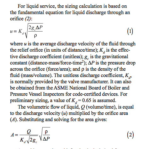
%D7%A6%D7%99%D7%9C%D7%95%D7%9D_%D7%9E%D7%A1%D7%9A_2018.11.30_%D7%91.14.34.37_qi6uf7.png


But there are a few things I don't really understand there:

1. First and foremost, I'm having a hard time understanding where is the orifice in such valves.
Many pictures of cross-section PRVs don't even use the word orifice when describing the valve's components.
On the following picture, is "valve-seat" (part 2) the actual orifice?
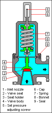
Relief_Valve_bnlheq.png

2. Regarding the first formula - what is DeltaP? Yes, it is the pressure drop across the orifice, but which pressure do they refer to?
The difference between the overpressure and the set pressure? It got me confused.
3. Regarding the second formula - they used Q there (volumetric flow of the liquid) but it is a parameter I also don't know! I mean, Q=VA, and on the first formula I found V, but I'm still left with 2 variables (Q and A) and they're just "finding" A by using Q whereas it is still unknown!

Would appreciate your help regarding these matters.
Thanks a lot!
 
Replies continue below

Recommended for you

For future reference you may get better feedback on the Safety Relief Valve Engineering (PSV) forum. But while we're here.

Get a copy of API 520 (Part 1) and 521. 520 contains the sizing equations that are used to size the orifice. 521 is more of a design guide that shows you how to analyze a system and what kind of failures to potentially consider (such as thermal expansion, closed outlet, etc). The equation snapshot you've posted is similar to the API 520 equation solving for A (orifice area).

1) The orifice is right at the red part below the seat holder. The bottom is the valve inlet and the conical shaped taper is called the nozzle. The spring (#7) on the valve pushes down on the seat holder to keep the valve normally closed. In simplistic terms, once system pressure exceed valve set pressure, the seat holder begins to rise and allow flow.
2) dP is across the valve here, yes. P1 is the relief pressure, typically set pressure + overpressure (10% for normal scenarios, 21% for fire). P2 would be the result of a backpressure calculation on the discharge piping, so it's an iterative process.
3) The Q (flow) here is the required relief flow, because you're trying to do initial relief valve sizing. Do not mix this flow with the nameplate capacity of the relief valve. Nameplate capacity must be greater than required flow.

The crux is finding the required relief flow for all your applicable scenarios. You have to look at the whole process and determine what scenarios are possible and figure out flows associated with them. For example, in a heat exchanger blocked outlet scenario, the design scenario may be based on the shutoff pump head.
 
@RVAmeche,
Thanks for the elaborated answer.
Unfortunately I don't think I fully understand 2. and 3. :(
Regarding 2: The backpressure you mentioned, is the "pressure downstream of the relief device, that includes the constant superimposed backpressure and the built-up backpressure due to the discharge of fluid from the relief device through the downstream piping"?
This is a complex definition I can't really comprehend. What should be calculated?
Regarding 3: I know that Q is the required relief flow. It is one of the variables in the problem. How come, then, it is used to calculate A? I don't know Q but they expect me to plug it in the equation for A?

And by the way - are there any tables that give A (orifice area) straight away, for given a pressure and fluid type & velocity? Something I can compare the calculation with to see that I'm not completely off the track.
 
P1 is essentially a known. You know your existing/proposed set pressure and the allowable overpressure for the scenario you're analyzing (10% or 21%).
P2 will depending on the discharge piping downstream of the relief valve. This has to do with backpressure (also defined well in API 520). Basically the more piping/fittings you have in the discharge piping, a higher pressure back at the relief valve will be seen. Also, if your piping is connected to a common header or relief tank, there may be other sources of backpressure such as the operating pressure of the tank or other relief valves going off in the header.

You need to know Q to find A. The standards like API 520 assume you've done the process engineer side of things and determined the flow rates for those cases. It just gives you guidance on calculating the required area and sizing the device. API 521 gives more guidance on reviewing the potential relief scenarios, but aside from cases like external fire or hydraulic expansion, API 521 also doesn't provide explicit equations to determine Q. It's up to you as the engineer to determine what the scenario is, what the parameters of that scenario are, and what the required relief rate Q are based on your process.

You're looking at this exercise in the wrong way. Sizing a relief valve, in general, is not "plug in values and get an answer". You have to think about your process. Hopefully you have a senior engineer around that will be mentoring you - go to him/her and pick their brains about the subject. It's not the type of thing where X + Y always equals Z. Every process is a little different, every vessel is different, and different scenarios could occur.
 
Status
Not open for further replies.

Part and Inventory Search

Sponsor