Continue to Site

Eng-Tips is the largest engineering community on the Internet

Intelligent Work Forums for Engineering Professionals

  • Congratulations KootK on being selected by the Eng-Tips community for having the most helpful posts in the forums last week. Way to Go!

Pressure required to shear screws. 2

Status
Not open for further replies.

CADCAMTech

Mechanical
Nov 10, 2015
33
I am trying to calculate the amount of force that is applied to a fitting, when an internal pressure is applied to it. The red line shows the area where the pressure is applied, the blue dot is the shear screws, and the yellow arrow is the direction the fitting moves when the screw shears. The end goal is to calculate the number of shear screws I will need.

Sliding_Sleeve_j85wir.png


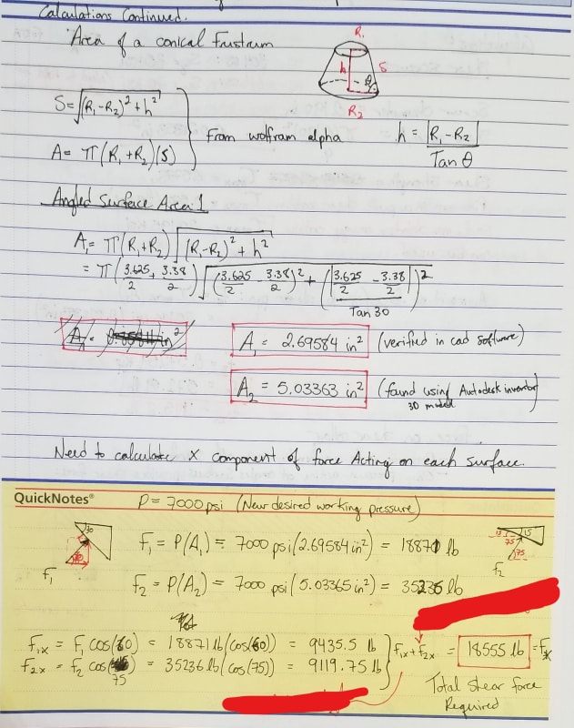
If you look at the attached images below you can see how I calculated the angled areas which I applied the 7000 psi pressure to. Then I calculated the force based on my known pressure and the known surface area with the pressure acting perpendicular to the surface, and finally I solved for the x direction of the force for each angled area.

The final value I ended up with (18871 lbf) was much larger than I was expecting and does not correlate with older data we have. Previous tests have shown that a pressure of approx. 3000 psi is needed to shear 3 screws, but this was all done by testing, no previous hand calculations exist for this product that I can find.

So I am wondering where I have went wrong:
1. When you look at F1 and F2 below, should I only be using the higher value instead of adding them together? To me both surfaces contribute to the force in the x-direction.​
2. I assumed that the max distortion energy criterion applied to the shear screws where shear=0.577Sy is this correct?​

If anyone is able to help point me in the right direction for what I am trying to do it would be appreciated, Thanks.

(to make things worse, I have no idea what the yield strength of the shears screws is. The drawing says it should be 304 SS at 35ksi min yield, but the PO I tracked down says the screws are 316 SS conforming to ASTM F880(CW) but no grade is listed and I have not been able to find out what that ASTM document specifies. I have hardness tested several of the screws and they seem to be around 96 HRB)
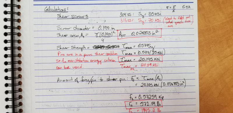
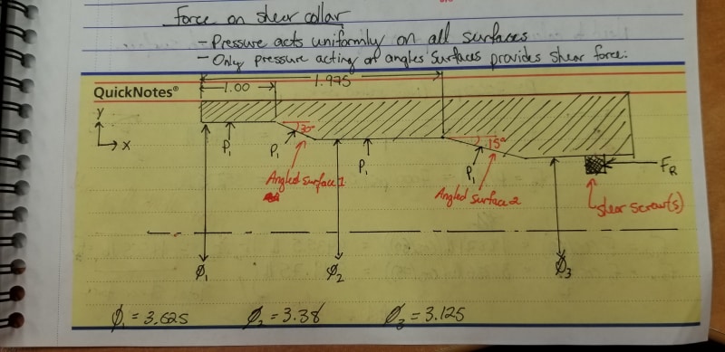
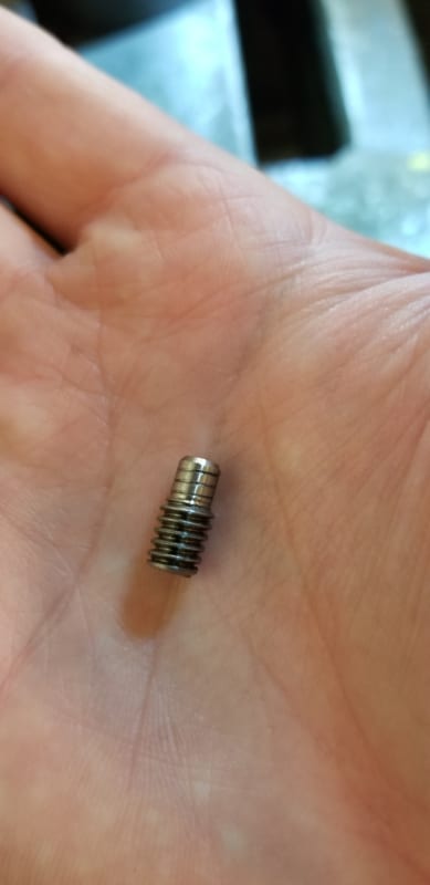
Shear_Screw_dz4pwn.jpg

Calculations_1_pvgbio.jpg

Calculations_2_hi5kr4.jpg
 
Replies continue below

Recommended for you

The only area that matters when calculating pressure force in the x-direction is the area projected on the y-z plane. So, just subtract the area of diameter 3 from the area of diameter 1.

In your example you are calculating the force perpendicular to the surfaces of the conical sections, not in the x-direction.

In your drawings you do not show any seals, so it is impossible for us to know if they actually truly model your actual problem. If the pressure gets to other area in your joint that could change the force considerably.
 
Compositepro,

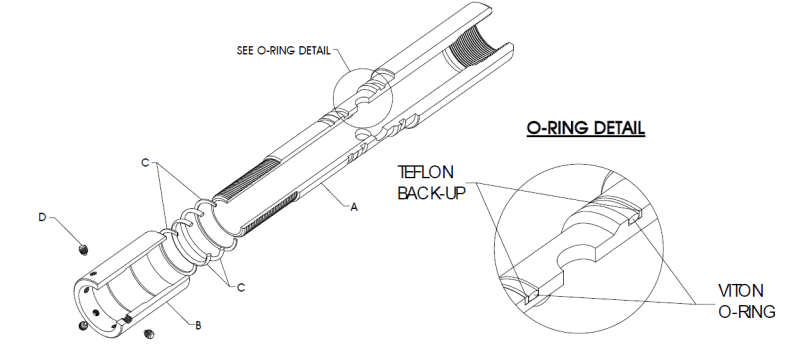
I have recalculated as you stated thanks for the clarification, I was going to do it that way initially by trying to think of it like a piston but was unsure if I could just do diameter 3-diameter 1 because of those angles faces and the fact that resulting force on them would act in the x and y directions. As for the seals, in the first image you can see a black o-ring in the middle of the image. There is also one on the upper end of the fitting. The pressure is confined between these two o-rings and we have never had one leak. There is only between a .001" - .003" extrusion gap for both of the o-rings and the rings are backed up with teflon.

I obviously over complicated things, thanks for your help.
 
Ok so I have done some testing of just the shear screws themselves by using a press instrumented with a pressure gauge, and then using the known piston diameter to calculate the force required to shear the screws. I got an average value of 3379 lbf to shear 3 screws. When we pressure the system up to 3000 psi we are able to shear 3 screws, and knowing that the projected surface area on the y-z plane is 2.65 in^2 I get a resultant force of 7950 lbf. This is basically double the value of 3379 lbf that I get from testing. If 3 screws shear at 3379 lbf by working backwards that should mean the internal pressure is 1275 psi on a 2.65 in^2 area.

So either I have some how screwed up the projected are calculation which I dont think I have because it should just be the area of the largest ID minus the area of the smallest ID. Or I am missing something else.

I can work this out just by adding screws until the screws shear at 7000 psi, but I would prefer to have the calculations to go with it.

Is any one able to see where I have went wrong?
 
Can you explain or draw this a bit more to understand what you did.

"using a press instrumented with a pressure gauge, and then using the known piston diameter to calculate the force required to shear the screws"

Where was the force being applied and how did you measure it / calculate it. Maybe this is where there is an error?

Remember - More details = better answers
Also: If you get a response it's polite to respond to it.
 
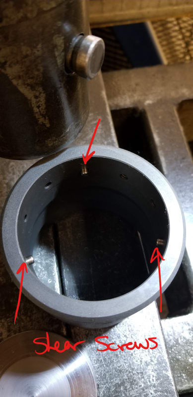
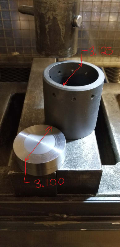
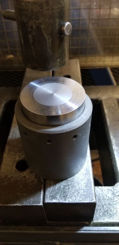
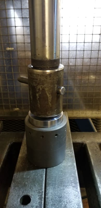
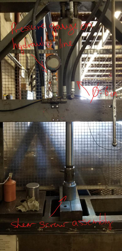
See the images below for how I have the shear tests setup. We have used this process many times for other projects where we have needed to know the force required to press/pull something and have had good success with it.
The pressure gauge is set to record the maximum value reached during each test.


Shear_Screw_ls81tb.jpg
Shear_Sleeve_ue37zi.jpg
Shear_Fixture_fpg8fg.jpg


20180712_085551_ihmmtp.jpg
Setup_pkvmrx.jpg
Press_mg2afw.jpg
 
For starters, shearing a bolt by pushing it against something flat and shearing a bolt by moving a part with a finely machined mating bore around the bolt are not really the same thing.
 
Do you mean pressure or force?

"Everyone is entitled to their own opinions, but they are not entitled to their own facts."
 
jgKRI,

You will have to further explain how that setup is different than say a bolt in single shear? You are right it is not the exact setup but I think it is the best way to approximate what happens when the assembly is pressured up. I am open for other suggestions if you have one.

ironic metallurgist,

Normally the the assembly seen below is pressured up using a hydrostatic test pump. When we use 3 shear screws, they generally break once the internal pressure reaches 3000 PSI. If i use the area between the coupling that holds the screws and what we would call the mandrel and multiply it by the pressure applied (2.65 in^2 x 3000 psi = 7950 lbf)I should get what the equivalent force applied to the shear screws by the shear coupling is.
 
You will get a closer result if the parts in your test setup are the same fit tolerances, and whatever surfaces carry load are the same shape, as the actual part.

I'm assuming that when your 3 screws are installed in the real part, they have preload on them, and aren't just loose in their holes. This will change the result.
 
jgKRI,

There is no significant pre-load on the screws, they are just slightly more than hand tight in some cases the customer may add loctite to ensure the screws don't back out. The screws have no purpose other than to shear at the right pressure. And the fit and tolerance is exactly the same as the groove that is cut in the mandrel, I made sure of that.
 
To add to Compositepro, I would have drawn a rectangular outline of the length and height( radial direction)of the red lined space on which the pressure would be acting. Knowing the separation between screws you can calculate the force acting in the longitudinal direction and that force equals the resisting shear force. No frictional resistance between mating parts is to be considered.
 
racookpe1978

The area calculation is good. Both your syntax and mine mean the exact same thing. I also double checked it in my CAD software so I know it is right.
 
Your thrust force calculation is correct, I assume your issue is the shear capacity of the pins being so much lower than the empirical shear force. Quite often these types of pins and grub screws have been work hardened, so you might find the yield strength is much higher than that used in your calculation. I would start by getting the material certificate from the pin supplier. There will also be a little bit of pin bending, the friction and other loses should be minor.

The pictures of your shear test rig look different to the 3D section view and calculation, looks like in your pictures the pins are cantilevered and sheared by the disc sitting on top. The pressure is applied to the hydraulic cylinder not internally. Is this a new concept you are developing? If so, how have you calculated your applied force from the hydraulic cylinder in the current testing?
 
BJI,
The first image below is the actual setup, the darker outside sleeve moves left to right when the pressure is applied.
The second image is the test setup the lighter plunger on the right side of the image moves right to left shearing the screw in the same direction it would shear under normal operation.

The only reason I started testing the screws using the hydraulic press, was because the shear values I was getting when pressure testing the unit did not match my hand calculated values. So I figured if I could focus on just the screws I could track down where the discrepancy was coming from. I used a piston with a known diameter and then read the cylinder pressure off of the hydraulic press line to calculate the force that the piston was applying to shear the screws.

I am still in the process of tracking down an MTR for the screws, all our internal documentation showed was that the screws were 316SS manufactured to ASME F880(CW). I have been unable to find what the typical mechanical properties in this condition are. If I dont have to buy the standard to figure it out that would be nice. I have done a Rockewell hardness test of several screws and got an average of around 91 HRB with readings as high as 96 HRB. Looking at the conversion of hardness to approximate tensile strength the screw should be in the 95-105 ksi range.
Actual_fs18go.png

Test_jkb3kg.png
 
Status
Not open for further replies.

Part and Inventory Search

Sponsor