Continue to Site

Eng-Tips is the largest engineering community on the Internet

Intelligent Work Forums for Engineering Professionals

  • Congratulations GregLocock on being selected by the Eng-Tips community for having the most helpful posts in the forums last week. Way to Go!

Pressure vessel design

Status
Not open for further replies.

perky416

Aerospace
Sep 4, 2011
14
Hi Guys,

Im in the process of adapting the pressure vessel on my air rifle to increase capacity.

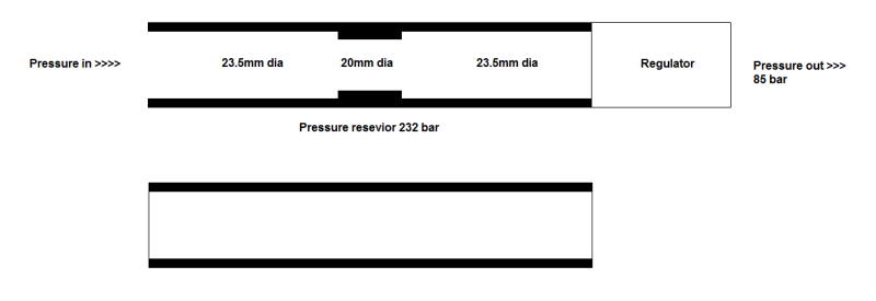
Please take a look at the image attached, is it acceptable for a pressure vessel to step down in size from 23.5mm to 20mm, and then back up again to 23.5mm? The step down in size is where 2 halves of the cylinder screw together.

Or is it absolutely necessary for a pressure vessel to be all one continuous size as in the bottom example?

The cylinder stores the pressure at 232bar.

Many Thanks
pressure_eewg45.png
 
Replies continue below

Recommended for you

The ID does not need to be uniform. That being said, 232 bar is VERY high pressure. You need to properly select the material, wall thickness of the shell, and the method of joining the parts together, etc... The risk of injury with this kind of pressure is real. I don't recommend a hobbyist experiment with this kind of stuff. It is common for vessels to be hydrotested at 1.3x the design pressure. Were you planning on doing this? Are you familiar with hydrotesting? I suspect not if you need to ask about the ID. I'm not trying to be a jerk, but your health and safety are more important than an air rifle.

Other opinions are welcome.

Edit:
Take a look at this table: The author suggests that the burst pressure of NPS 1 XXS is 32,700 psi (225 bar). You are literally building a pipe bomb.
 
Hi perky416

I recommend also that you don't attempt this!
Screwing two halves of a pressure vessel without following any design code is asking for trouble particularly when the pressure vessel is storing a gas, if you get it wrong then boom the whole thing will go off like a grenade.

“Do not worry about your problems with mathematics, I assure you mine are far greater.” Albert Einstein
 
Hi Guys,

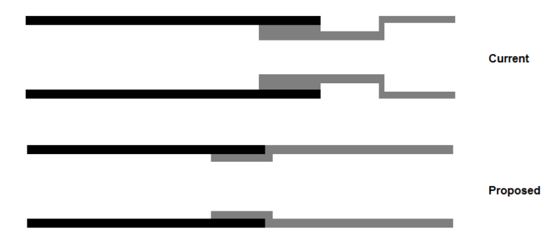
Thanks for the concern. I have uploaded another picture with both parts highlighted different colors, the top part is showing the current set up, the bottom the proposed set up.

The grey part in the top picture is made from 4140 Chrome Molybdeen steel and the main body has a wall thickness of 2.25mm. The reason it is designed as it is, is so that another part can fit over where the OD is at its smallest. This part is not needed so id like to do away with it.

pressure2_mefvuc.png


The original part is joined using an M25 x 1.0 thread and sealed with an o-ring. I propose to still use an M25 x 1.0 thread but seal it with PTFE tape. Still keeping a wall thickness of 2.25mm and using 4140 CM steel.

I used the following equation:
Pressure = 2 * Yield Strength * Wall Thickness / Outside Diameter * Safety Factor
Using the yeld strength of 4140 and a safety factor of 1.5 I calculate that it can take around 447 bar before it begins to deform.

As you can imagine i've never had much experience dealing with pressure and I understand it can be dangerous. I am trying to take the proper precautions by using current material and dimensions.

All help greatly appreciated
 
DON'T DO IT!

Not only are you risking the life and safety of yourself and other people who come near the vessel, but you aren't really gaining anything as far as I can see.

Also, that is not the formula that I am familiar with for allowable pressure. I don't have any experience with thick-walled pressure vessels, so maybe this is the correct formula, but I doubt it.

You also need to consider the strength of the thread engagement. If the PV wall is thick enough that it doesn't explode, but the threads are strong enough, then instead of a grenade you'll have a rocket.
 
Hi pperlich,

Without meaning to sound rude, I appreciate all responses, but why do you doubt that is the correct formula to use? It is Barlows formula for calculating the internal pressure that a pipe can withstand. It was also mentioned in the link that keyen provided.

I am gaining extra cylinder volume meaning an increased air capacity.

I will be using the same thread, same material & same wall thickness as the original part.

Also to test I was planning on filling it with water and pumping it to 1.5x pressure to avoid an explosion, it will just fracture and burst (yes I understand a jet of high pressure water can cut through skin like a knife, this has also been taken into consideration), however after looking into hydrotesting as mentioned by keyen I plan on testing to 385 bar water pressure.

Whilst I appreciate all concern, I started off my career as a machinist and have worked in the aerospace industry for 10 years, this industry revolves around health and safety and risk assessments.
I have previously made brass and aluminium fill valves on my lathe for the very same air rifle (and they are a weaker material than 4140 CM), using exactly the same thread just at the opposite end of the cylinder to the regulator, they were designed, calculated, manufactured, tested and used with success.
I am not a teenager playing silly buggers in my garden shed. I was simply unsure if the ID needed to be uniform or not as I understand that pressure flows better with a smooth unobstructed surface.

Regards
 
Hi perky416
The ratio of wall thickness to the bore ID might well make this a thick walled vessel where the stress distribution is different for a thin walled vessel or pipe, also reducing the vessel down and then up again well produce complex stress raiser which might well fail due to fatigue after a period of use, so its not quite so simple as appling a formula.

We have to be careful how we respond to posts that can be potentially dangerous, as we don't really know anything about each other and even given some background, again we cannot be sure who we are dealing with.
Lets face it I could claim to be an astronaut, brain surgeon or anything else I fancy.

“Do not worry about your problems with mathematics, I assure you mine are far greater.” Albert Einstein
 
For thin-walled PV's that I deal with an allowable stress value is used to determine pressure limits. The allowable stress is typically the lesser of the yield stress divided by 1.5 or tensile stress divided by 3.5.
But like I said. I think you will have a thick-walled pressure for which I have almost zero experience.

To answer you original question: It depends on the flow rate of the air. If you expect the PV to empty completely in a very short time frame, then the ID difference may have a small effect. If only a small amount of the air is released at a time then it shouldn't make a difference in a practical sense.

Fatigue would be a major concern for me. You would be wise to use a large radius in your corners. The sharper the corner, the higher the stress concentration, which will lead to a fatigue failure.
 
Trying to seal a parallel thread with PTFE tape sounds like a good excuse to come back and do the whole job again the other way next week. If you need to move away from the O Ring seal, consider using a Dowty instead.

2.25 instinctively feels quite thin for a 232 bar steel cylinder - I appreciate that it's a narrow bottle (which makes a big difference) - but then you're cutting x1.0 threads in a pressurised section of the wall? (All very well saying it was like that before, but as soon as you adapt the design, the whole thing becomes yours - bad bits as well as good).

Depending on where you are in the world, the law starts taking an interest in pressure vessels unexpectedly early on in their journey from "garden shed" via "out in public" to "in the workplace". In many cases, that point comes where you first try to carry the cylinder anywhere in a road vehicle. Recognising that your aim is to increase the cylinder capacity, one thing you ought to check is whether your existing design is actually relying on that peculiar reduction in volume to keep it exempt from the most onerous bits of legislation (for example if you happen to be within the EU, as soon as your cylinder grows beyond 215 ml WC, the design and design-proving requirements multiply beyond all recognition. Laws elsewhere vary in detail, but most make some sort of distinction between very small bottles and the rest).

Why have you chosen a 385 bar test pressure? 348 would be more usual (and there's no benefit to inflicting more low-cycle fatigue damage on the material than you absolutely need to).

A.
 
Interesting subject. I would put a little more meet in the barrel wall thickness. Your weak Pont is on the threaded union. Of you can just socket weld it wit out threading may be a lot better joint. Also using a forged drilled barrel may be a lot better. good luck.
 
2.25 mm does seem small for that kind of pressure. Even if the pressure calculation shows that it is thick enough, you need to add extra thickness in case your rifle gets bumped or dropped or dented. You also need to account for manufacturing undertolerance.


Status
Not open for further replies.

Part and Inventory Search

Sponsor