Hello,
I hope everyone is doing fine, at first I would like to apologize for not replying on my last post a few months ago, as it seems there was a technical issue at my end preventing me from receiving the notification emails !!! and special thanks for the extremely useful replied.
now for the subject here, with reference to (Pressure Vessel Design Manual, 4th edition, by Moss), I do have some questions please:
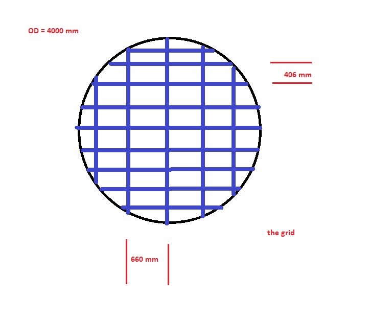
I am reading and trying to understand the strength calculation records of an existing vertical vessel which has got a bed of catalyst resting on a mesh tied to a grid, then support ring, and 5 beams below, and although the part of calculations related to internals is referring to the above mentioned book as the reference (the calculations are performed by some excel sheet probably as it had some minor typing errors such as area in m3 etc...), now what is a bit confusing is that they dont follow the book exactly, and even in the book some equations result units dont make sense to me ....
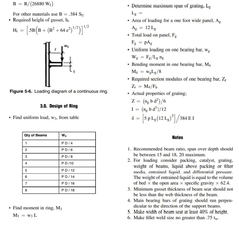
1- for the support grid/grating: in the calculations documents they used a load width (B) of 1000 mm (in the book they suggested a 1 foot length to calculate the area then moment), and they call it max load width, however its different from max span length of 660 mm .. however unlike what the book says that you need to count the number of bearing bars in the panel, they just calculated the entire grid Z and I by multiplying the I and Z of the grid bar section into number of bars in the entire grid, not only the panel area of 1000 x 660 !! and if I follow the book, the bending moment in one bar M4 comes in Kg only not kg-mm or lb-in as it is supposed !! I have attached some screens below for reference ...
2- in the grid calculations as well, the max deflection equation in the book is = [ 5 p Lg (12Lg)^3 ] / 384 E I ... were 12 is the 1 foot (12 inchs) which is width of loading area as suggested by the book, using this equation gives some off values if you cube the number 12, however in the calculations they only used this = [5 p lg^4 x B]/384 E I ... am I missing something here?
3- in the grid attached , what is ng suggested in the book here if I take B as 1000 mm? is it 3 ??
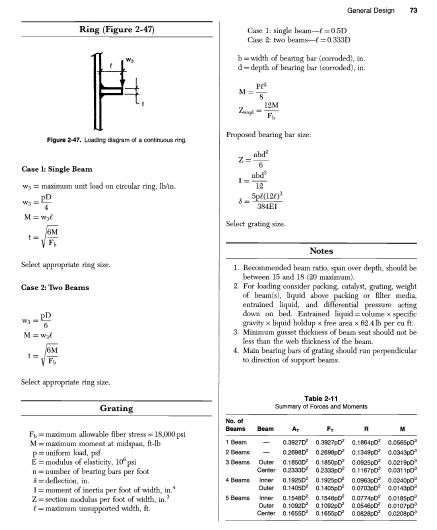
3- the support ring calculations are quite simple, however again in the book page 306 the moment in ring M3 = w3 L , but if you calculate this you get moment units of Kgs only (or lbs) , so in the calculations documents they fixed this by making the unit kg - mm/mm , i.e. multiplying by mm/mm to get it as moment .. and it works fine this way in the thickness equation .. my understanding is this is because the uniform load here is circular so the moment is per mm or circumference ?? not sure though ...
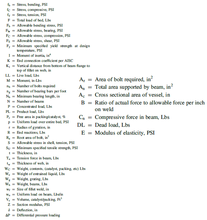
4- for the beams table in the book page 303 , I have 2 questions please: in the equations below there is fT=Tn/AT , what is AT here as it is missing from notations table even ..
Thanks alot & Regards,


