Eng-Tips is the largest engineering community on the Internet

Intelligent Work Forums for Engineering Professionals

  • Congratulations waross on being selected by the Eng-Tips community for having the most helpful posts in the forums last week. Way to Go!

prestressing bed abutment 2

Status
Not open for further replies.

Prestressed Guy

Structural
May 11, 2007
390
US
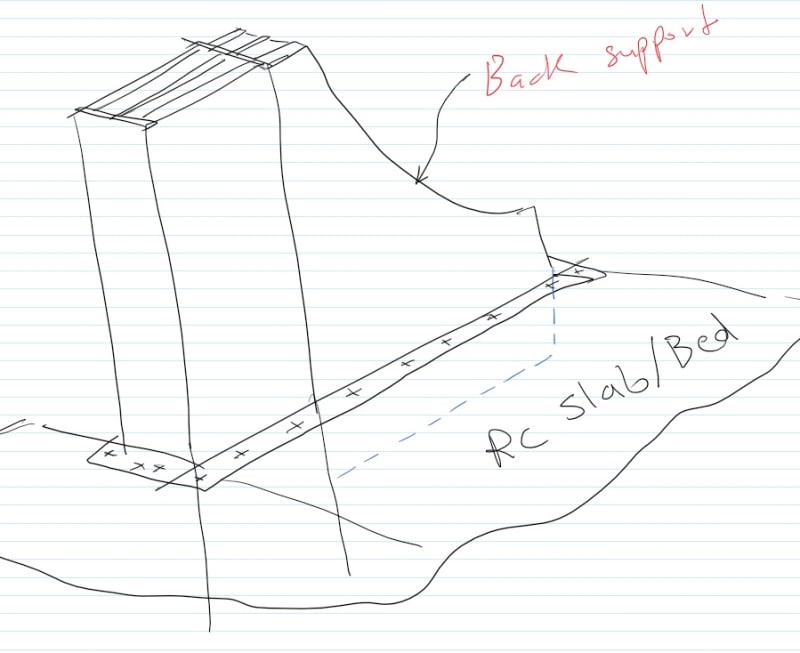
I am reviewing this abutment design that was sent to me for a prestressed girder bed and thought I might get some feed back from the collective.

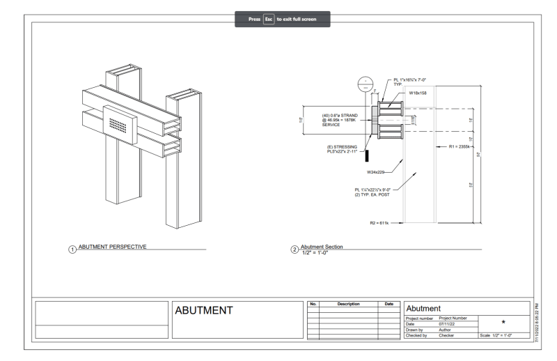
The STRESSING PL5"x22"x 2'-11" is existing and it is hoped that it can be reused. Given the required loads, it can span about 10". To me, this use would appear to load only the W18 web and one of the 1" lateral plates but not both. I also will produce significant torsion in the built-up W18 which would require web stiffeners at the bearings to prevent lateral distortion at the ends and should probably also have them at the center.

What say you?
Abutment_fjgiwb.png
 
Replies continue below

Recommended for you

Some big kips there!

Is the 5" bearing plate attached to the flanges of the W18's? The upper W18 eccentricity is equal but of opposite sign to the lower W18 eccentricity. Can you provide end-restraint and 'lace' the two 'exterior' W18 flanges together as the 'interior' flanges pass over the vertical W24's?

Also, I do not think your R1 and R2 reactions are not in static equilibrium.
 
@ Prestressed Guy
did worked for similar application
[large steel sections W18X158 behave quite elastic like spring and easily deflect]
so do as much you could stiffeners and back-support
Since every small inclination will twist your anchoring PLATE [Cause stress concentration around strands perimeter ]

Prestressed_Abutment_i4p87j.jpg


Prestressed_Abutment-2_yvbvhy.jpg
 
Ingenuity said:
Some big kips there!

Is the 5" bearing plate attached to the flanges of the W18's? The upper W18 eccentricity is equal but of opposite sign to the lower W18 eccentricity. Can you provide end-restraint and 'lace' the two 'exterior' W18 flanges together as the 'interior' flanges pass over the vertical W24's?

Also, I do not think your R1 and R2 reactions are not in static equilibrium.
Yep, big kips!
The 5" bearing plate is a loose item which is clamped to the horizontal strongback with threaded rods and can be moved sideways up to 9".

The reactions are from the worst case for the posts which is where the bearing plate is offset 9".

All of these items are loose. The horizontal strongbacks are also clamped to the posts so that they vertical location of the strand group can be adjusted.
 
adn26 said:
@ Prestressed Guy
did worked for similar application
[large steel sections W18X158 behave quite elastic like spring and easily deflect]
so do as much you could stiffeners and back-support
Since every small inclination will twist your anchoring PLATE [Cause stress concentration around strands perimeter ]
cl/cl of the posts is 6' and the W18x158 with (2) 1" thick x continuous side plates has an I[sub]y[/sub] = 4384in[sup]4[/sup] That will come to a deflection of about 1/16". The W24x229 with (2) 1¼" thick x continuous side plates has an I[sub]y[/sub] = 11,445in[sup]4[/sup]
The total accumulated design displacement of the system at the strand is just a bit more than 1/4"
 

Let's assume moment is 1878kips*2.5ft.
I wonder how you can transfer this huge moment to concrete/soil.
Sometimes stability problem happens with underground structure (concrete, soil)
rather than exposed steel structure.
 
what kind of foundation you are using ?
large mass concrete "L" or anchored mass concrete or ???
 
The bed is an existing gravity bed and has a mass footing with a 3'-6" x 7'-0" x 5'-0" deep bearing socket for the posts. It will have a fitted compression strut to hold the bottom of the post against the front wall.
 
Due to available steel sections, these abutment posts have been changed to W27x368 which have the required moment capacity but are short of the required 1880k of shear. We will be adding a 1" web doubler from the lower cross beam to the top support which gets øV up to 1945k. We plan to put a pair of web stiffeners on each side at 9" o.c. centered on each load and reaction to prevent web sidesways buckling or web bending (in-plane rotation of the free flange) but I am not sure how to size the thickness of a web stiffener that is welded to a 2.46" flange.

Any suggestions as to how thick to make them?
 
Prestressed Guy:
When you deal with structures like these, with highly concentrated loads, non-symmetry of loads w.r.t. your members, non-unifrom loads, etc., you quickly discover that you are not doing yourself any favors by starting out trying to work around rolled shapes (like WF’s) to build up your primary members, and their details. For some of the very reasons you have already suggested; one web loaded much more than others, WF web over stressed, etc.

I would start by building my own built-up box beams, and I have some good share of the weight of that W27 or W18, which I wouldn’t use, to place material where I found it most advantageous. On the posts, the two flgs. are sized for bending stresses, but probably not 14.665" x 2.48" in size. The webs nearest the 5" stressing block would be much thicker to take that imbalanced load and shear and bearing stresses, that you saw, and the outer webs could be thinner, but still to make a box section which would tolerate the torsional loading, etc. You start building from the inside-out to locate various stiffeners for bearing loads, etc., and finally put on the last flg. or web, by welding from the outside only, where the stresses can tolerate this. The same goes for the cross beams, get rid of the W18, and give me the 158lbs/ft to place where I rally need/want it.

You talked about being able to move the 5" stressing blk. left or rt., and to be able to move it up or down, in some increments, hopefully not infinitely adjustable. In the first case, I assume you just move the stressing blk. left or rt. on the cross beams, and the beams don’t move w.r.t. each other. In the second case, the stressing blk. and the cross beams move up or down as a unit. I think there are a number of other things/details which might be improvements, but you’ve left out so many details about the actual situation, it’s hard to know.
 
Status
Not open for further replies.

Part and Inventory Search

Sponsor

Back
Top