Raniel Albuquerque
Petroleum
Hello,
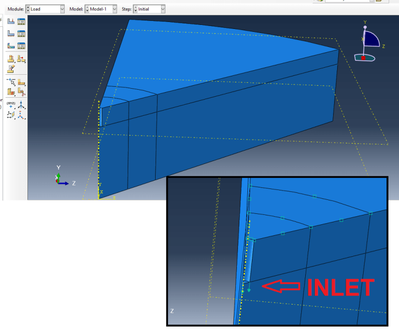
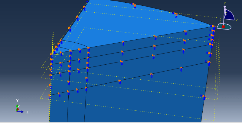
I'm simulating a Fluid-structure interaction of a water jet perforating a soil. In order to reduce computational time, I'm trying to apply symmetry conditions to my problem, which consists in two models, one fluid and another solid. The fluid model doesn't allowes the creation of an axissymetric part, and how the fluid model and the solid model must have a interface of interaction, I can't apply the convencional symmetry. So I'm trying to use the boundary conditions to simulate the symmetry. But my solid model results are strange.
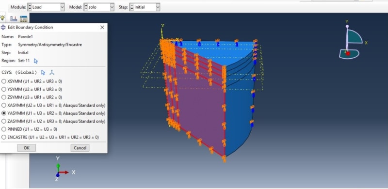
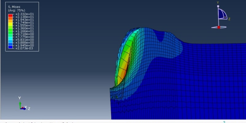
When I use the Symmetry/Antisymmetry/Encastre condition, with U1 = U3 = UR2 = 0, the soil's lateral walls aren't moving down, but the inner region is. I've constrained only the X and Z axis displacements, it should've move down with the inner region.
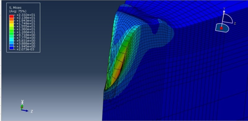
Any thoughts how I could solve this problem, by means of the correct use of symmetry or changing some elements properties?
I'm simulating a Fluid-structure interaction of a water jet perforating a soil. In order to reduce computational time, I'm trying to apply symmetry conditions to my problem, which consists in two models, one fluid and another solid. The fluid model doesn't allowes the creation of an axissymetric part, and how the fluid model and the solid model must have a interface of interaction, I can't apply the convencional symmetry. So I'm trying to use the boundary conditions to simulate the symmetry. But my solid model results are strange.
When I use the Symmetry/Antisymmetry/Encastre condition, with U1 = U3 = UR2 = 0, the soil's lateral walls aren't moving down, but the inner region is. I've constrained only the X and Z axis displacements, it should've move down with the inner region.


Any thoughts how I could solve this problem, by means of the correct use of symmetry or changing some elements properties?

