Eng-Tips is the largest engineering community on the Internet

Intelligent Work Forums for Engineering Professionals

  • Congratulations waross on being selected by the Tek-Tips community for having the most helpful posts in the forums last week. Way to Go!

Proper LMC Callout 1

Status
Not open for further replies.

abrewmaster

Mechanical
Aug 15, 2013
20
0
0
US
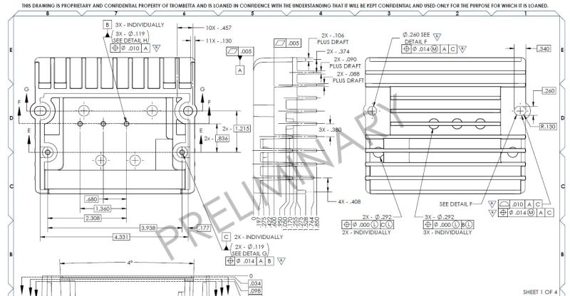
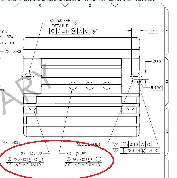
So I have a boss with a blind hole going into it and want to ensure a minimum wall thickness if either the hole or boss moves or changes diameter but want to give bonus tolerance so that the part isn't rejected.

It seems like the LMC callout is what I need for both the location as well as datum B (assuming datum B is the hole going into the boss) to convey the condition that when both the hole and boss are both at their LMC then the parts have to be dead nuts on one another but anything other than that you get bonus tolerance for the boss to move around. Is what I have drawn right now conveying that correctly or is it supposed to be called out differently? I wasn't able to find anything exactly like this online or in the ASME book that describes something like this.

LMC_GD_T_Question_s9yara.jpg
 
Replies continue below

Recommended for you

abrewmaster:

The LMC concept can communicate the design intent - wall thickness - you described. But be aware, the tolerance zone (mating envelope) is "in the metal" and requires calculations based on surface analysis. This demands careful planning from a QA standpoint to confirm requirements.

Certified Sr. GD&T Professional
 
INDIVIDUALLY is used when a datum feature is repeated. It looks like C is not repeated. SEPARATE REQUIREMENT is used if the features are to be evaluated separately.
 
First, no bonus tolerance will be added because there is no tolerances on Dia 0.292. You need to show Datums B & C to properly understand the position frame. It is chopped from the image.
 
3DDave has a good point. What is the intent of using the term "INDIVIDUALLY"? And...are the (5) holes one pattern or are there two patterns of holes - group f 2 and a group of 3? So are you using the term to separate the patterns or the holes in each pattern - assuming there are two patterns?


Certified Sr. GD&T Professional
 
Thanks for the feedback so far guys.

There are two sets of patterns as you seem to have guessed. The two sets of holes are on different planes which is probably more evident with the new picture I attached. I believe the INDIVIDUALLY is valid here since the datum feature is repeated but I have only used the callout a couple of times before so I might be using it wrong.

mkcski said:
The LMC concept can communicate the design intent - wall thickness - you described. But be aware, the tolerance zone (mating envelope) is "in the metal" and requires calculations based on surface analysis. This demands careful planning from a QA standpoint to confirm requirements.
Is there a better way to achive the same result or is it something our Quality department has to accept will involve some work? when I talked about what I wanted to do they seemed like they would be able to do it, granted they weren't the most excited.

Pyromech said:
First, no bonus tolerance will be added because there is no tolerances on Dia 0.292. You need to show Datums B & C to properly understand the position frame. It is chopped from the image.
The title block has standard tolerances of +/-.005" so the LMC should be .287" Attached is a view that shows datums B and C as well.

LMC_GD_T_Question_-_2_vpe6ey.jpg
 
One other thing to remember is that when you specify a FOS with LMC modifier it turns rule #1 on its head. Perfect form is now required at LMC size, not at MMC size for that FOS. And, yes, as mentioned by Mkcski the bonus is now taken from the size of the actual minimum material envelope (the low points, inside the material).

Based upon size limits of the hole and the boss and the LMC FCFs you are able to calculate what the minimum wall thickness allowed is. This is what QA needs to verify (along with correct size). If you were not using GD&T there would most likely be a note stating the minimum allowable wall thickness for these features. Although that note might lead to the measurement being taken with calipers. So, the LMC FCF is superior to a wall thickness note, in that it clearly describes how that minimum thickness needs to be thought of.
 
Status
Not open for further replies.
Back
Top