Hey!
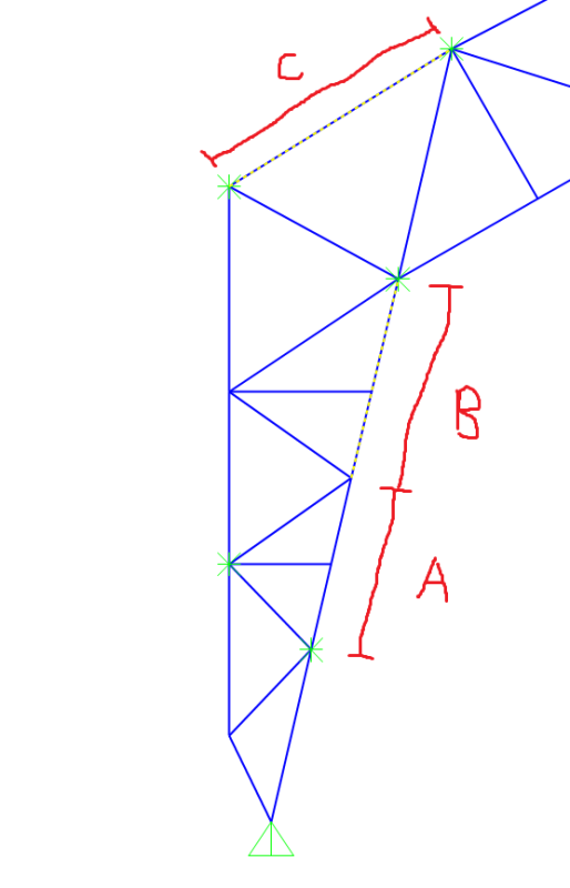
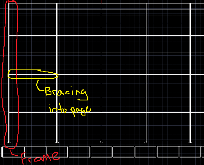
Here I have the leg of a frame and I'm trying to model the frame members properly so that the unbraced length is accurate to what it is in real life. To explain, along the inside of the leg the member spans A+B and is only restrained transitionally INTO the page at the green joints shown. Now I've looked up the axis of the members and the global axis to try to restrain the members A+B at the bottom of A and top of B (green joints) so that the program will assume the unbraced length into the page is A+B, but it doesn't. Instead it takes the literal drawing member length (member highlighted) and uses A or B independently for the steel design. I labelled "C" to show that if the member length works out to be in between the bracing then properly modelled. How would you combat this? I'm sure Sap2000 is capable of assuming these lengths. I've only tried the "Restraint Joint" Option since I'm unsure what the difference is between a constrain and restraint in this program. Any help would be appreciated, thanks in advance!
Here I have the leg of a frame and I'm trying to model the frame members properly so that the unbraced length is accurate to what it is in real life. To explain, along the inside of the leg the member spans A+B and is only restrained transitionally INTO the page at the green joints shown. Now I've looked up the axis of the members and the global axis to try to restrain the members A+B at the bottom of A and top of B (green joints) so that the program will assume the unbraced length into the page is A+B, but it doesn't. Instead it takes the literal drawing member length (member highlighted) and uses A or B independently for the steel design. I labelled "C" to show that if the member length works out to be in between the bracing then properly modelled. How would you combat this? I'm sure Sap2000 is capable of assuming these lengths. I've only tried the "Restraint Joint" Option since I'm unsure what the difference is between a constrain and restraint in this program. Any help would be appreciated, thanks in advance!