Continue to Site

Eng-Tips is the largest engineering community on the Internet

Intelligent Work Forums for Engineering Professionals

  • Congratulations GregLocock on being selected by the Eng-Tips community for having the most helpful posts in the forums last week. Way to Go!

Property Modifier for Built-up Section (SAP2000)

Status
Not open for further replies.

neukcm

Structural
May 3, 2015
63
Hi,

I am currently using v17 2.0 of SAP2000 and understands that design for steel built - up section is limited for I section, cover plated I and Hybrid U. My section is welded box and i am using section designer to model it (sometimes TUBE section) but somehow confused of the calculated property as it may differ from the actual built up. I'm aware that SAP2000 section designer considers the defined section as one unit and definitely will ignore connection between plate.

Is there any property modifier that i can use for Box Built up section defined in Section Designer? I mean to reduced the stiffness and take into account the effect of welded parts.

Thanks
Neukcm
 
Replies continue below

Recommended for you

In property modifier, you can reduce torsional/axial/bending stiffness depending on your need. One means 100%, reduce it based on ur case.

Cheers
 
Mohandes,

Thanks. Is there any specific value that i can use when it comes to built up section? I mean built up section property differs from that of a section which is defined or customized using Sap section designer. I tried an I section, first using built up I Section and second i tried modelling the same I Section using Section Designer and found out some discrepancy in their properties. I am using box section with outstand flange and i want to account for the connection of each part (welds) but when i modelled it using Section Designer, Sap consider it as a whole piece, unity member.

And just want to ask, How does Sap2000 treats section defined in Section Designer? I mean what particular assumption does it use specially in Eurocode 3?

Thanks,
Neukcm
 
I'm not sure about EC, I never used section designer. Did you check the "watch and learn video 12"? I know that SAP recalculates all the properties based on defined section.
 
Mohandes,

I have a question and it is not actually related on top.

Does SAP2000 able to design steel plates just like other FEA softwares? If not do you have any idea of designing plates or how to determine if the plate is pass or failed in a certain loading condition given that you have only stresses as the output? Say for example Stress S11, how can i determine if my plate is not overstressed? Is it by comparing to material grade say S275 then apply reduction factor? Straight forward approach?

I'm sorry for this general question i just want to have an idea of designing plates.

Cheers,
Neukcm
 
Yes, SAP does design steel plates. First of all, you need to determine what type of elements you are using, notably plate, membrane thick and thin shell elements. If you are not sure then I suggest to go through SAP documentation for details but mainly membrane is for in-plane deformation, plate for ou-f plane, thin shell no shear deformation and thick shell with shear deformation. Once you have your element, regardless of user-defined section or built-in section, SAP gives stresses at several points. If you know the material properties (which you should know), then easily you can decide the range of stress in the output by using contour with the desired range. Simple as that, you can find out about the failure of the plate.

Cheers
 
Mohandes,

Good to know that SAP2000 was able to design steel plates whether it is thin or thick elements. I am just beginning to understand SAP2000 as it is by far the most suitable software for our projects. Thanks for the time and effort explaining the above matter, well understood.

I haven't tried analyzing structure with membrane mostly shell (thin plate elements) as our sections is usually built up/welded. As i told you, i always end up with stresses (S11, S12, S13, Smax and Smin)but don't know how to interpret the data and compare to my material properties. I know the grade of my material say S275, S355, etc and the necessary reduction factors. I need to go thru EC3 specs for plated structures for material prop and the allowable stresses for shell elements as you have mentioned. I will check out also that contour stress in the documentation for clearer vision of my query. Can i assume area edge constraints on for every welded connection of plates? How about the deflection of the plate is it calculated also?

Thank you once again!
Neukcm
 
Area dge constraint for mimicking full rigid connection, apply it as necessary. As I said earlier, in SAP output you can get stress/force/deflection of any element. Just simply make a quick simply supported plate with point load, then you see all the information you need there (importance of practicing!)

Cheers

 
Mohandes,

Sorry to extend this thread again. I have two things to ask you:

a) I am using SAP2000 - FEA extensively (as we discussed previously) for my structure and been confused which resulting stress is to use, currently i'm using the maximum stress in the report table (Plate Element Stresses Output) either Smax/min for TOP or Smax/min for BOttom. However, included in the stress output is the Von Mises Stress calculation which is somehow smaller. Which one should i adopt? Thanks

b) (Please find attached) I have tried modelling a plate 25mm THK with an opening at the middle and apply concentrated load on top nodes only (-500kN, exaggerated load). I am expecting that my plate would buckle but it doesn't, SAP2000 displacement result is quite confusing which shows that the plate will just deflect vertically on its axis. Then i change the thickness of plate to 5mm but still i got the same result. Vertical displacement along its axis,. Is there something wrong with my model? or Boundary conditions? or my meshing? Thanks in advance for the insight. Appreciated much!

neukcm
 
 http://files.engineering.com/getfile.aspx?folder=65f3773e-482c-482b-9f03-862a782237ac&file=TRIAL.pdf
I just got noticed reply was made to this thread!

for 1st question, it is important what you are looking for. Of course SAP2K or any other software gives as much details as you want, but you only pick up what you're looking for. FOr your case, what is the purpose of your analysis? what you want to get? Besides, do you know the local direction of shell elements you have used? Is your output based on local axis or global axis? I strognly recommend you have a look at (Link) and Link. FOr more details, refer to manual (I know it is cumbersome to go through it and read all those lengthy pages, but believe me mate, software learning is only by trial and; and every case is dependant). So you need to have full confidence for each separate analysis

For 22nd question, what analysis have you considered? what are the restraint applied in your boundary conditions? Is the load being transformed through meshing? Is meshing have connectivity? From what I see in the screenshot, it looks to me your boundary condition and meshing are entirely wrong! What I suggest you do is to Google simple plate with holes examples in Abaqus and Ansys as such types of fine meshing is easily carried out in these software. See how they applied loading, meshing, support fixity and consideration of large deflection to take place( indeed if you run normal static/dynamic analysis without effect of large deformation theory, then you will not have significant buckling).

Try to do a simple plate/shell element, then perform parametric study; meaning you observe the effect of variation in support, meshing and analysis on the output, then move on to more complex problems.

Cheers

Shoot for the Moon, even if U miss, U still land among Stars!
 
Mohandes,

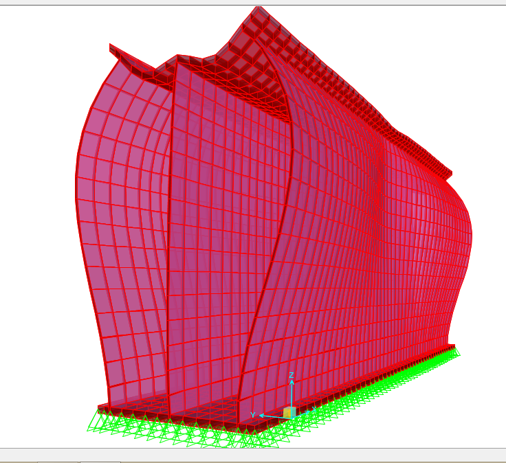
1) 1st question: Actually i am designing a box girder comprised of plates welded together (see attached image). This box will be subjected to a 400-ton load, uniformly distributed on the top flange and i am concern of how the plates will behave, buckling or yielding failure so i ended up modelling the box girder as a finite model (mesh plates). I created a square mesh to allow joint connectivity between each plates. I understand the local and global direction of plate elements as i am going thru the SAP2000 manual. But i just ended up confused of the results or maybe i need to widen up my understanding of finite element analysis. Thanks for the link.

2) 2nd question: I apply linear analysis for the box girder and i assume fixed restraint for welded joints. The load is uniformly distributed on top of flange and have it applied as pressure.

Thanks bro, i'm learning thru discussing these Things to you. Thanks for the time and effort explaining.

NEUKCM
BOX_GIRDER_ajyjzh.png
 
Lucky I was online :D

Is this box girder? it doesn't look like one to me!
why do you use 400t loading? what kind of design specification you are using?
Is your shell elements thick or thin?
Support at base I can guarantee is completely wrong.

I recommend you go with CSiBridge to model this steel plate box girder, since readily available deck sections can significantly help you out in modelling; plus it has wide range of vehicular loading.

Best,


Shoot for the Moon, even if U miss, U still land among Stars!
 
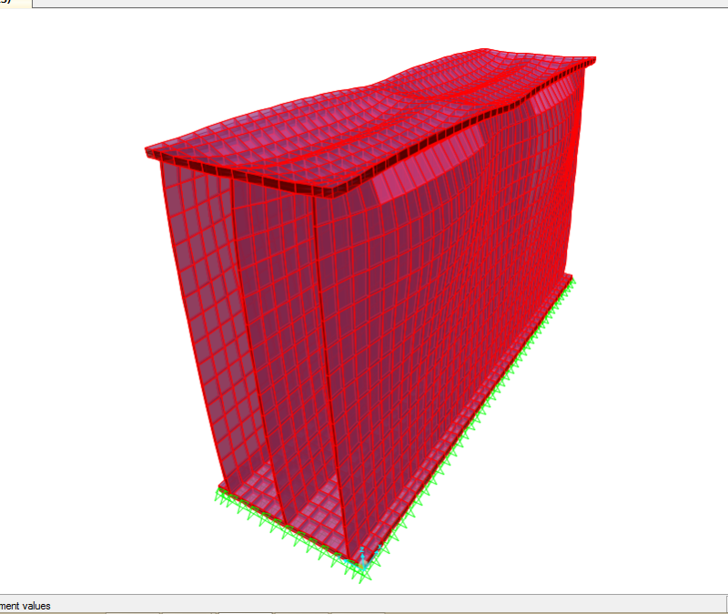
Sorry i forgot to mention that this is the deflected shape of the box girder without stiffeners inside. This is a 2.0m length box beam; 1.2m depth x 0.6m width. This beam is actually 72 pcs all in all that will support a stationary ship onshore and i have just analyze one piece. We are under Eurocode and my shell element is thin: Flange thickness (top/bot) = 25mm, web thickness = 9mm.

The 72 pcs beam (2.0m length) will rest directly on the ground while supporting the ship on top. :D What should be my base support then?
Thanks! Please find attached another view of the box beam.

Screenshot_180_wmbl3p.png
 
If you want to model ground, you need to consider spring elements with appropriate stiffness which I reckon you don't have the data, then instead use suitable support fixity at reasonable spacing. I told you before, sometimes you need to use engineering judgment, that's how e do as engineers!
For EU, I recall SAP2K can check against the minimum stresses for steel profiles. Why don't you use user-defined or predefined steel section and let the software check the stresses for you? Shell elements are sorta complicated as output is hugely affected by meshing and connectivity of joints.

I believe we've been stretching this thread for some time and now need to give room to other people too. So I consider it as resolved thread as sufficient explanation have been provided so far.

Cheers,


Shoot for the Moon, even if U miss, U still land among Stars!
 
I don't think using SAP2000 user pre-defined steel section will be close for this kind of analysis. This will be more on local analysis and buckling might be involve. Indeed shell elements are sorta complicated, but being complex doesn't mean you can't do it or you will stop doing it and try the simpler analysis- this is not the engineer's way of solving problems.

Anyway thanks for sharing but based from the data you have given to me i think i really need to go far and dig deeper.

cheers

 
Status
Not open for further replies.

Part and Inventory Search

Sponsor