Eng-Tips is the largest engineering community on the Internet

Intelligent Work Forums for Engineering Professionals

  • Congratulations waross on being selected by the Tek-Tips community for having the most helpful posts in the forums last week. Way to Go!

PSV outlet pipe reduction - incompressible liquid discharge 1

Status
Not open for further replies.

pskk

Chemical
May 12, 2020
1
0
0
PT
Dear all,

I am working on a desalter revamp and I have a question.
The existing desalter has a 3L4 valve with a 4" outlet line discharging to the main header. The 4" line is at most 5 m long.
This PSV has to be replaced for a 4M6 valve but the outlet line has to be the same 4" line (main header can't be hot tapped so we can't make a tie-in there).

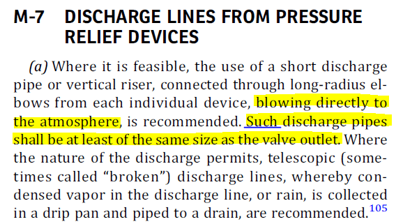
I see everyone stating that the discharge line of a PSV shall have an equal or higher diameter than PSV's outlet nozzle.
I totally understand that rule if we are dealing with compressible fluids.
However, most people seem to blindly follow that rule even when we are talking about incompressible liquids.

In this case, I would have a 6" outlet nozzle and a 4" discharge line (5 meters only) discharging to the main header.

Why can't we do this if we dealing with incompressible liquids?
Why is 4" pipe OK for inlet but it isn't for the outlet? A liquid won't expand that much so I don't really get it.
If the pressure loss is within our acceptable range, I honestly don't get why I can't do that besides "looking bad".

Can you guys please enlighten me?

Sincerely,
Pedro


Replies continue below

Recommended for you

If the inlet piping of PSV can be replaced from 3" to 4", why the outlet pipe can't be changed.

I wonder if it's a good design excuse to deviate the Code because of the issue of the hot-tapped of the header pipe.

 
It sounds like the existing valve was undersized or the new one is oversized.

Either way I don't think pointing to existing conditions is a good excuse to deviate from Code.

Your calcs with the new 4M6 relief valve, when relieving at it's higher capacity, show that the 4" discharge piping, header, and whatever the header empties into results in acceptable backpressure?
 
I don't see anywhere in the ASME BPVC code that requires the PSV discharge piping to be equal to or greater than the discharge flange connection.

From UG-135

(1) The opening through all pipe, fittings, and nonreclosing pressure relief devices (if installed) between a
pressure vessel and its pressure relief valve shall have at
least the area of the pressure relief valve inlet. The characteristics of this upstream system shall be such that the
pressure drop will not reduce the relieving capacity below
that required or adversely affect the proper operation of
the pressure relief valve


and also in UG-135:

The size of the discharge lines shall
be such that any pressure that may exist or develop will
not reduce the relieving capacity of the pressure relief devices below that required to properly protect the vessel, or
adversely affect the proper operation of the pressure relief
devices .


The only requirement for discharge piping being equal to the orifice size is in UG-127 when using the "flow resistance method" for rupture discs and pin devices, which does not address relief valves at all.

There are some more requirements about allowable maximum backpressure on the PSV, but I don't see anything about nominal discharge pipe diameter. I don't think what you stated in your OP is a code requirement. Does anyone see any specific clauses that contradict that statement?
 
I'm also not aware of this requirement for discharge piping, as questioned by TiCl4. Would like to know a specific clause for this too if it exists.

If it complies with backpressure requirements (hence my initial question) I think it's ok, albeit I would replace the piping in the next available turnaround even if it's only due to an aesthetic issue.

Daniel
Rio de Janeiro - Brazil
 
The ASME Sec VIII outlet piping requirement is in Appendix M rather than in the main body. Refer to M-7 Discharge Lines From Pressure Relief Devices. That paragraph starts with a recommendation, saying to use a short discharge line whenever it's feasible to do so. Then it states..."Such discharge pipes shall be at least the same size as the valve outlet."

So what is the purpose of this M-7 requirement? It's intended to minimize the risk of the tailpipe causing excessive flow restrictions and/or excessive built-up backpressure. That's the same reason for the inlet line requirement which says that the inlet line must have at least as much open area as the PRV inlet.

For new installations this isn't a problem - it's easy to comply with this and there's rarely a new installation where we find that this is causing any significant waste of money. It's the existing installations where this sometimes presents us with a problem. We sometimes find, for example, that there's a need to replace the existing PRV with the next size larger one. We do the calculations and find that the existing piping is OK - we're able to get the necessary flow rate and the pressure drop is within the code limits - but the pipe size doesn't comply with this ASME requirements. If you're in a jurisdiction where ASME compliance is a legal requirement, then your stuck with following the requirement even though your installation satisfies the intent of the requirement. If you're in a jurisdiction where ASME compliance isn't a legal requirement then you have a legitimate argument that the installation is OK, despite not strictly complying with the code.
 
You cannot avoid the statutory requirement to calculate the built up backpressure on this RV for the design case relief load for the piping configuration you've got, to confirm this is within the permissible limits for the type of RV you've got.
 
Don,

In my understanding, that paragraph applies to piping discharging directly to the atmosphere, which I don't think it is the case in OP's (by the way, where is he?) scenario.

Also, wouldn't Appendix M be nonmandatory? I'm not too familiarized with legal requirements, but wouldn't it just be a recommended practice?

Daniel
Rio de Janeiro - Brazil
 
A "non-mandatory" appendix in a code always seems like a catch 22 to me.

Yes, technically/legally it is not required. However if an incident occurs and it turns out the damage was a result of not following the "non-mandatory" appendix published in a code, I suspect the lawyers/OSHA/whoever will be quick to point out you failed to follow RAGAGEP (recognized and generally accepted good engineering practice).

For my stamp, I'm following that non-mandatory appendix unless the client is absolutely adamant I don't, which would then be documented in my relief valve calculations as well.

That's to say nothing of manufacturer recommendations. I'm quite sure every manufacturer says installations require <= 3% losses on inlet and 10% losses on outlet for conventional relief valves. So now your installation goes against good practice AND manufacturer instructions. You lose that battle, no matter how "non-mandatory" it is.
 
RVA,

I agree that it should be followed whenever feasible too.

But in OP's specific case, do you think it is really non-compliant to the code? We know nothing about the backpressure developed in his discharge piping and, if I correctly interpreted Appendix M's paragraph regarding directly-to-atmosphere discharge, his case would be different, no?

I'm just trying to be the devil's advocate here. If it were me leading this project I would increase the discharge piping diameter too.

Daniel
Rio de Janeiro - Brazil
 
I agree we need more details from OP.

I don't think anything about M-7 restricts it to direct atmospheric discharges. It would be weird if it did, since superimposed backpressure is a common consideration when doing the calculations.
 
Well, english is not my first language so the "such" here is what confuses me:

appm_s0paus.png


Daniel
Rio de Janeiro - Brazil
 
Edit - I think I misread what you said. I thought you meant all of M-7 only applied to atmospheric discharges.

It does seem that the "pipe size at least the valve outlet size" point could be argued as a limit to direct discharges only, but the 10% rule is still a requirement within M-7.
 
RVA,

I'm sorry if at any moment I seemed to disagree with the 3% / 10% rule! It should be within those limits (for a 10% overpressure valve) in every situation.

My specific issue with the clauses is specifically related to the diameter itself. If his 4" pipe with a reduction immediately downstream of the discharge nozzle (plus all the other existing flowpath in the header) doesn't surpass the 10% rule at the new rated flow (that will be higher, naturally), paired with the direct discharge conundrum, I 'think' it may be within the code's requirements.

In the end, it will probably be a matter of how brave he is though.

Daniel
Rio de Janeiro - Brazil
 
Don, thanks for the find. However, I still don't think that provision applies to the OP's situation.

From M-7.
(a) Where it is feasible, the use of a short discharge pipe
or vertical riser, connected through long‐radius elbows
from each individual device, blowing directly to the atmosphere, is recommended. Such discharge pipes shall be at
least of the same size as the valve outlet.
Where the nature
of the discharge permits, telescopic (sometimes called
“broken”) discharge lines, whereby condensed vapor in
the discharge line, or rain, is collected in a drip pan and
piped to a drain, are recommended.


When it says "such discharge pipes", I read that as referring to short discharge pipes that discharge directly to atmosphere - i.e. a "short discharge pipe". I also read the stipulation of "Such discharge pipes..." as meaning the size requirement only applies to the aforementioned "short discharge pipe". This is bolstered by the fact that M-7 then continues on in part (b)

(b) When discharge lines are long, or where outlets of two or more devices having set pressures within a comparable range are connected into a common line, the effect of the back pressure that may be developed therein when certain devices operate must be considered [see UG-135(f)].

No mention of a size requirement for "long" discharge lines, but rather puts the burden of proof on the designer to prove pressure drop is acceptable.

Lastly, M-7, part (d) says:
(d) All discharge lines shall be run as direct as is practicable to the point of final release for disposal. For the longer lines, due consideration shall be given to the advantage of long‐radius elbows, avoidance of closeup fittings, and the minimizing of excessive line strains by expansion joints and well‐known means of support to minimize line‐sway and vibration under operating conditions.

It seems clear to me that the code makes a distinction between "short discharge lines" (addressed in M-7 (a) and "long discharge lines" (addressed in M-7 (b)), especially since part (d) refers to "all" discharge lines. It also seems clear that the requirement for discharge piping size only applies to the "short discharge lines".

A final supporting point is a corollary : rupture disc relieving capacity requirements in UG-127 also make a distinction between "short" and "longer" discharge lines. "Short" lines have an inlet and exit discharge nominal size requirement in UG-127 (2)(-a)(-1), while "longer" lines simply stipulate (in (2)(-a)(-2) that total resistance to flow must be considered, with no requirement on outlet pipe diameter.

Overall, I don't believe this is a code requirement. Thoughts on this?
 
Naturally one would think that Appendix M isn't a legal requirement anywhere because it has "non-mandatory" in the title. But that hasn't stopped legal authorities in the US (e.g. US OSHA, and authorities in some US states) from enforcing it as mandatory requirements. OSHA gets around the "non-mandatory" part by making it a legal requirement to conform to RAGAGEP (Recognized And Generally Accepted Good Engineering Practices) and there are a number of Appendix-M "requirements" which they actively enforce (e.g. the securement of isolation valves ("stop valves"), and the 3% rule which is in APP-M). But there's plenty of "grey area" in interpreting what is and what is not RAGAGEP. For example, the APP-M outlet piping requirement that we're discussing isn't in API 520 Pt II, which is also regarded as a RAGAGEP standard. And BTW, API 520 Pt II allows the use of engineering analysis as an alternative to the 3% rule, and this has been grudgingly accepted by OSHA. OSHA likes things to be simple ("black & white") which is why they like the 3% rule, and why they resisted acceptance of engineering analysis as a technically valid alternate method for assessing PRV stability. Ironically, there's no technical validity to the 3% rule, but it sure makes enforcement simple - they like that.

For facilities outside the US, in jurisdictions that adopt ASME Sec VIII, these code interpretations are much easier. The word non-mandatory means what it says it means.

As for whether M-7(a) applies exclusively for tailpipes that discharge to atm, the text doesn't state or imply such a limitation. I read M-7(a) as applying to all tailpipes, regardless of where they are routed. There's nothing in that paragraph that leads me to interpret it as just applying to tailpipes routed to atm. Paragraph (d) doesn't contradict that interpretation. It just adds further info.

BTW, I saw several posts above which stated there's a fixed 10% pressure loss limit ("built-up backpressure" limit) for all PRV outlet pipes. This is a common misunderstanding that can unnecessarily cause you to waste money in some installations. Built-up backpressure is limited to 10%, or the amount of the overpressure that's built into that specific design, whichever is greater. If the PRV is set at the MAWP, then the limit is 10% for non-fire cases (the allowable overpressure is 10%). If the PRV is set at the MAWP, and the only credible scenario is fire exposure, then the limit is 21% (because the overpressure is 21% in this case). If the PRV is set below the MAWP, then the alowable built-up backpressure limit is even higher - equal to the overpressure, whatever that value is for that case. This is explained in API 520 Pt II. This basis for this may not be intuitively obvious, until you think it through (or better yet, write out the simple arithmetic for the force balance equation). You'll see that the net force balance on the PRV is exactly the same valve, for each case in which the built-up backpressure equals the overpressure. Higher built-up backpressure values don't affect the PRV as long as it is offset by the overpressure.
 
Status
Not open for further replies.
Back
Top