Continue to Site

Eng-Tips is the largest engineering community on the Internet

Intelligent Work Forums for Engineering Professionals

  • Congratulations 3DDave on being selected by the Eng-Tips community for having the most helpful posts in the forums last week. Way to Go!

Pump 1st stage Impeller damage mechanism for barrel type Water injection pump 4

Status
Not open for further replies.

Mech5656

Mechanical
Aug 2, 2014
127
Hello Dear Engineers,

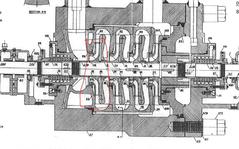
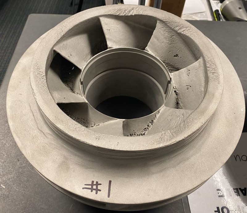
As you may have noticed from my other posts, I am working to study pump components damage mechanism. I found another impeller damage due possible cavitation and wanted to share with you to get your feedback on damage mechanisms. This is suction impeller (first stage) for water injection pump that is used in oil field. Noticed the area where impeller ring sits apart from cavitation damage. What can possibly cause that?

suction_impeller_e9x2az.jpg
 
Replies continue below

Recommended for you

What I see that is unusual is that the cavitation forms behind a vane but stays up on the impeller eye. This says to me that there is insufficient flow velocity through the impeller to carry the bubble down through the flow path. Perhaps this pump is operating too far to the left on its pump curve and is overheating.
 
What does this sit into?

Got a sectional drawing of the inlet chamber?

Does the flow then turn 90 degrees and exit from the outside of the impellor?

Bit difficult to tell from only one photo tbh.


Remember - More details = better answers
Also: If you get a response it's polite to respond to it.
 
TugboatEng:
Thank you for your reponse. That is a good observation. Thank you!

LittleInch:

The process fluid is jet water and pump is used in decoking process of refinery, where the remains of crude oil from distillation is refined further (coker unit).

Below is the pump sectional highlighted impeller shown in picture.

sectional_j9fzxs.jpg
 
I can't really see the impellor wear ring surface but it looks heavily scored implying considerable flow perhaps from the outlet side back into the inlet.

Flow into the eye of the impellor looks quite complex.

A lot will depend on how the pump was operated, fluid conditions, temperature, pressure flow etc.

Was it allowed to dead head for long periods?

Remember - More details = better answers
Also: If you get a response it's polite to respond to it.
 
Suction recirculation cavitation damage.
The pump is pobably running away from its BEP.

It is a capital mistake to theorise before one has data. Insensibly one begins to twist facts to suit theories, instead of theories to suit facts. (Sherlock Holmes - A Scandal in Bohemia.)
 
The damage along the roots of the vanes looks like cavitation.
The damage to the rim looks like it could be erosion or excessive recirculation (way off of BEP and or end play).
The hole in the mid-vane is a typical casting defect with wear piled on top of it.

= = = = = = = = = = = = = = = = = = = =
P.E. Metallurgy, consulting work welcomed
 
Thank you all for replying.

The application is application. Can you recommend a material for this impeller that has cavitation resistance against this kind of damage and has high corrosion resistant. In other words, what material will resist this kind of damage the most? Edstainless?
 
Cavitation resistance? The 300 series stainless steels have very good cavitation resistance. If you need more you're going to need to go with rubber. What temperatures are we talking?
 
Tugboat:
Thanks for quick response. Operating temp is max 110F
 
Before going down the road of material change you should carefully evaluate the pump performance capabilities against the actual operating conditions. That means a thorough controlled accurate performance test at and around the performance conditions compared to any documented factory testing.

For me, a material change is probably unnecessary as it is likely a hydraulic performance problem.
My suggestion is to contact the pump manufacturer for advice on the application.

It is a capital mistake to theorise before one has data. Insensibly one begins to twist facts to suit theories, instead of theories to suit facts. (Sherlock Holmes - A Scandal in Bohemia.)
 
What is the current material?

= = = = = = = = = = = = = = = = = = = =
P.E. Metallurgy, consulting work welcomed
 
From the picture shared, it does not look like cavitation effect. Kindly look for these possibilities for assessment .
1. Water recirculation due to low sizer impeller fitted in casing. Please check cut water length and impeller dia.
2. Check for impeller material. Non-standard impeller can cause this problem too.

 
Artisi:
The operating point will stay the same. You can call it bad original design impeller or necessity to run the pump off from BEP. I know it will happen again but what material will resist this kind of damage the most and last the longest out of all materials?

EdStainless:
The material of impeller shown in above picture 17-4 PH SST.
 
Rubber is the most cavitation resistant material. 110°F is acceptable for a rubber coated application.

But ,if you're operating far to the left on the pump curve there may not be sufficient flow for cooling local temperatures may be higher
 
who is the pump manufacturer, what model is it and what duty was the pump selected to meet and what is the actual operating duty, how long has the pump been in operation, is this a new or ongoing problem?

It is a capital mistake to theorise before one has data. Insensibly one begins to twist facts to suit theories, instead of theories to suit facts. (Sherlock Holmes - A Scandal in Bohemia.)
 
So this is the cast version of 17-4PH, what is the heat treatment?
It should have been solution annealed and then aged, what is the aging temperature?
The edges look like erosion, which is a different animal to deal with.


= = = = = = = = = = = = = = = = = = = =
P.E. Metallurgy, consulting work welcomed
 
EdStainless: agree erosion appears in many places and was noted for later discussion.

Establishing actual performance against selection is the first step, once known it will eliminate a lot of questions and point to a likely resolution, however at this point I don't see it solely material problem.

Changing material just for the sake of guess work is like closing the stable gate after the horse has escaped - the question is "why was the gate open" and will go round and round for want of meaningful information.


It is a capital mistake to theorise before one has data. Insensibly one begins to twist facts to suit theories, instead of theories to suit facts. (Sherlock Holmes - A Scandal in Bohemia.)
 
Artisi ! Looking at impeller's condition, it can be either material's issue or design issue. Other possibility could be operational fault (discharge valve remains open and causes water to circulate inside casing) which is rare possibility.
 
Daren Samy, following a life-time in the pump industry involved with sales, application, design, trouble shooting it is my experience that the majority of pump problems result from wrong hydraulic selection or wrong application or duty change without considering the changes on the pump hydraulic capabilities. Material problem for a correctly selected pump is rare, and a design issue from a reputable manufacturer is extremely rare.

At the moment, we have no manufacturer, application data, performance curve versus actual site operating conditions etc - therefore its all crystal ball gazing and spinning wheels.

It is a capital mistake to theorise before one has data. Insensibly one begins to twist facts to suit theories, instead of theories to suit facts. (Sherlock Holmes - A Scandal in Bohemia.)
 
Status
Not open for further replies.

Part and Inventory Search

Sponsor