Dear pump experts
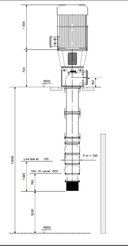
In my project, I have 3 vertical turbine pumps, controlled by PLC. Normal operation is if washing is required for 7 seawater screening Drums 2 pump will start. if only 3 Drum screens are in operation one pump only will start. 3 bar pressure and 52 m.cube /hr of water supply is required for each Drum for backwash operation. Our supplier has given me the following Pump curve. It shows If one pump is working the head is 52 m and Q= 210 m.cube/hr. But if two pumps are working Q= 420 m3/hr and H= 52m. Also shown are other values when one pump is in operation 288 cu.m /hr @29 m . That confused me . . I raised the following question to the Vendor to understand the curve
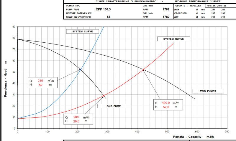
Qusetion) Dear Vendor, My understanding is that there is only one system curve whether one pump is working or two pumps are working. Only the pump curve adds up as you have shown in the pump curve. Since the System curve has a slope the flow couldn’t add up to 420 m3/hr. from 210 and 210 m3/hr. Otherwise, in parallel flow 210, m3/hr. of each 2 pumps will not give 420m3/hr. in combination.
Reply) In our Pump Curve, we represented N.2 system curves considering that you could increment the system curve slope using regulating valve on the discharge. If you haven’t regulating valve, when from two pumps running you have one pump running and the same system curve, the pump will work at 288m3/h @29m.
Reply Ends.......
There is no modulating Valve to control the flow to each Drum. We use a Motorised gate valve with just ON and OFF positions only.
I couldn't understand his reply. I could be wrong in my question. I am confused when he showed one pump with 210 m/hr and another curve showing one pump with different values,i.e 288m3/hr and 29 m head. How is this possible,one pump working with two performance?
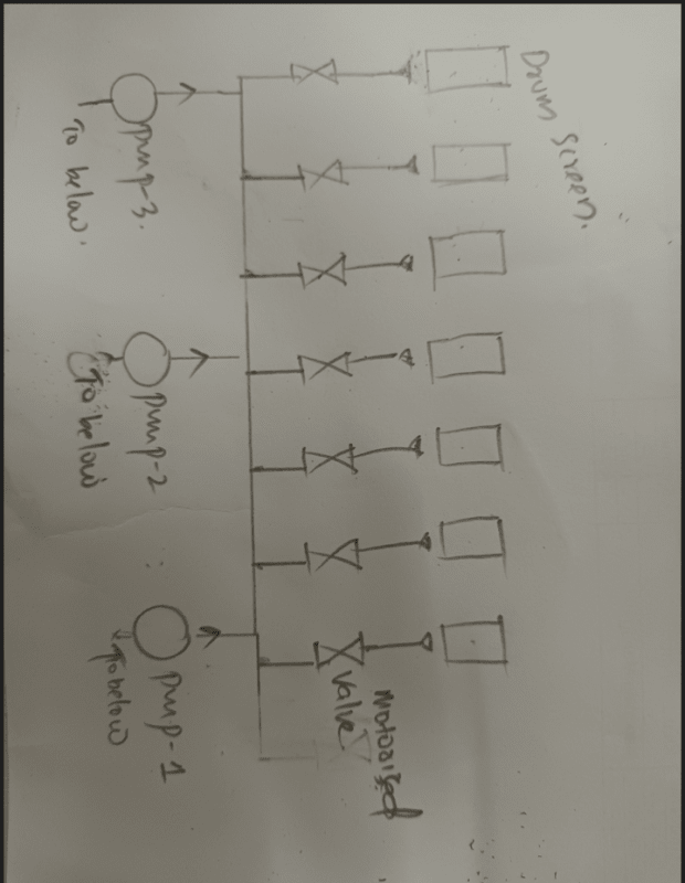
In my project, I have 3 vertical turbine pumps, controlled by PLC. Normal operation is if washing is required for 7 seawater screening Drums 2 pump will start. if only 3 Drum screens are in operation one pump only will start. 3 bar pressure and 52 m.cube /hr of water supply is required for each Drum for backwash operation. Our supplier has given me the following Pump curve. It shows If one pump is working the head is 52 m and Q= 210 m.cube/hr. But if two pumps are working Q= 420 m3/hr and H= 52m. Also shown are other values when one pump is in operation 288 cu.m /hr @29 m . That confused me . . I raised the following question to the Vendor to understand the curve
Qusetion) Dear Vendor, My understanding is that there is only one system curve whether one pump is working or two pumps are working. Only the pump curve adds up as you have shown in the pump curve. Since the System curve has a slope the flow couldn’t add up to 420 m3/hr. from 210 and 210 m3/hr. Otherwise, in parallel flow 210, m3/hr. of each 2 pumps will not give 420m3/hr. in combination.
Reply) In our Pump Curve, we represented N.2 system curves considering that you could increment the system curve slope using regulating valve on the discharge. If you haven’t regulating valve, when from two pumps running you have one pump running and the same system curve, the pump will work at 288m3/h @29m.
Reply Ends.......
There is no modulating Valve to control the flow to each Drum. We use a Motorised gate valve with just ON and OFF positions only.
I couldn't understand his reply. I could be wrong in my question. I am confused when he showed one pump with 210 m/hr and another curve showing one pump with different values,i.e 288m3/hr and 29 m head. How is this possible,one pump working with two performance?