Continue to Site

Eng-Tips is the largest engineering community on the Internet

Intelligent Work Forums for Engineering Professionals

  • Congratulations IDS on being selected by the Eng-Tips community for having the most helpful posts in the forums last week. Way to Go!

Pump curve 4

Status
Not open for further replies.

asifraza0

Chemical
May 29, 2006
62
Hello Experts:

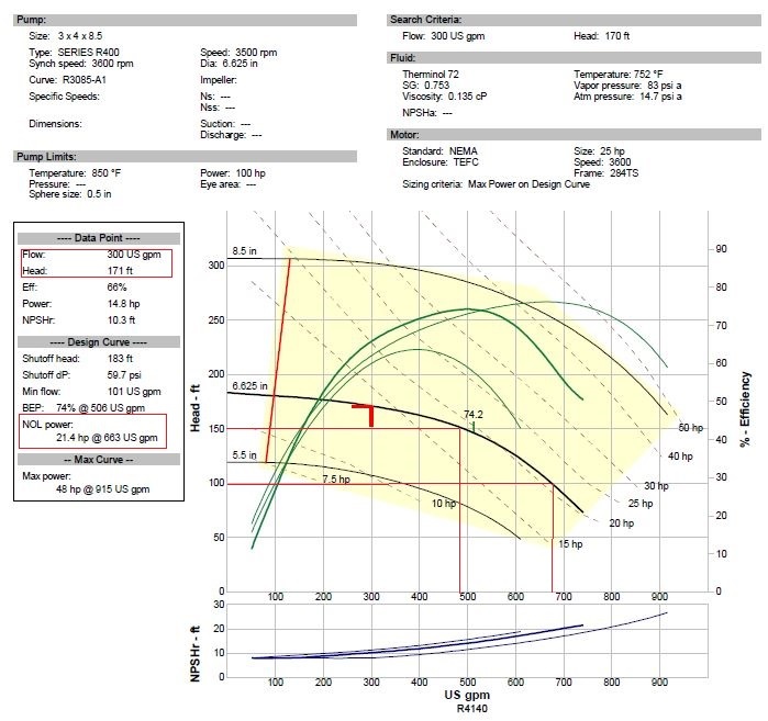
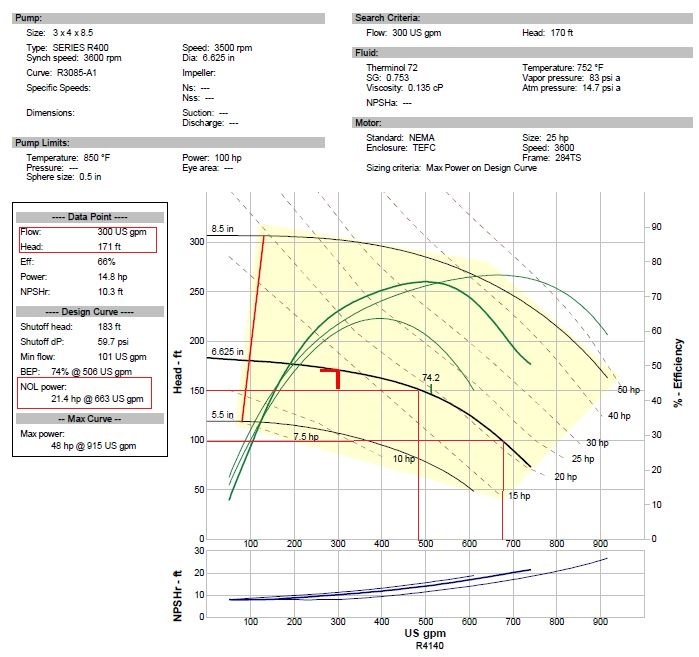
I need an expert opinion: I have a centrifugal pump running in thermic fluid service. The original design data sheet indicates the pump was sized for 300 GPM at 171 feet of diff head. The design of the pump is based existing and future expansion project. The expansion is yet to come. Having said that, the pump was put into service and the pump operated at 650 gpm at 100 feet of head. This was beyond the maximum allowable the pump could handle. The pump was operating very far right hand side of the curve. This resulted in shaft deflection and mechanical seal failures. The problem was diagnosed and the pump was put back on curve. Now the pump is operating at 480 GPM and 150 feet of head and very close to BEP. Currently the pump operation is very quiet and running smooth as a silk
Questions -
1) Is there any advantage in moving pump more towards the left hand side of the curve more closer to 300 GPM, the original design
2) If Nothing was done and the pump kept churning around 480 GPM; is there any concern with respect to higher velocity in the pipes and cavitation due to higher pressure drop in the suction. Since the piping size and the NPSH requirement is based on 300 GPM but in reality the output is 480 GPM

Thanks in advance for all your help
Araza


Asif Raza
 
Replies continue below

Recommended for you

Many times one will find that pumps are misapplied when originally installed. That appears to be what happened at your facility. Perhaps the pump impeller was changed after installation so that the pump would operate satisfactorily.

If you are running at the BEP, that is the optimum operating point and you will obtain satisfactory results with the pump.

The piping is probably 4-Inch or 6-Inch. Likely 6-Inch. In either case, the velocities do not seem to be extreme.

If cavitation was a problem with the existing pump and piping, the effects would already have been observed. The cavitation will have a more costly effect on the pump than the piping.

Since cavitation does not seem to be a problem and the pump is operating near the BEP, there will be limited opportunities to improve the system.
 
Please post pump curve

It is a capital mistake to theorise before one has data. Insensibly one begins to twist facts to suit theories, instead of theories to suit facts. (Sherlock Holmes - A Scandal in Bohemia.)
 
pump curve enclosed
Pump_curve_dc7yls.jpg
Pump_curve_mjqlxe.jpg


Asif Raza
 
I agree with bimr, if the pump is operating ok and the additional flow isn't a problem leave it be.
However, you could impose a bit more head by closing down on a discharge valve and shifting the flow to the left if considered necessary.

It is a capital mistake to theorise before one has data. Insensibly one begins to twist facts to suit theories, instead of theories to suit facts. (Sherlock Holmes - A Scandal in Bohemia.)
 
Or trim the impeller to suit the requirement.

It is a capital mistake to theorise before one has data. Insensibly one begins to twist facts to suit theories, instead of theories to suit facts. (Sherlock Holmes - A Scandal in Bohemia.)
 
I'm curios as to how "and the pump was put back on curve" was achieved. Can you add some more detail?

In answer to your points
1) If your service is Ok at 300 GPM, then you would reduce power consumption by about 5bhp / 3 kW

2) Not really an issue. NPSHR only increases by about 2 feet and if it runs well now then its all ok.


Remember - More details = better answers
Also: If you get a response it's polite to respond to it.
 
LittleInch: crystal ball off line today?

It is a capital mistake to theorise before one has data. Insensibly one begins to twist facts to suit theories, instead of theories to suit facts. (Sherlock Holmes - A Scandal in Bohemia.)
 
LittleInch:
I throttled valves at the outlet of the heat exchangers and closed the pressure control valves (bypass valve) at the end of the header. This way the discharge pressure went up and the pump was put back on the curve. Currently pump is riding very close to its BEP
Kind Regards,
Araza

Asif Raza
 
At the present time, stay the course with the operating improvements that you developed. When the time comes for pump replacement, purchase a pump that is correctly sized.
 
Thought it might be something like that. If those valves are standard isolating valves then you will be doing damage to them long term. You may also be altering the flow path it there are parallel has. Also what you should do is change the set point of the pressure control valves.

Be careful just doing changes without thinking them through.

Remember - More details = better answers
Also: If you get a response it's polite to respond to it.
 
Bimr:
what you would do in this scenario?
I require about 330 GPM at 130 feet of head
I'm thinking of trimming the impeller. Once i get the new curves I'll post it for discussion


Asif Raza
 
But you OP said the system was 600 gpm at 100 ft head. So 330 at 130 ft would still need some extra head loss.

What about your future expansion?

Remember - More details = better answers
Also: If you get a response it's polite to respond to it.
 
LittleInch:
With the current setup the requirement is 220 GPM at 100 feet of head. With the expansion project, the requirement will increase to 330 GPM at 130 feet.
So I can trim the impeller, this way I can reduce flow
Araza

Asif Raza
 
LittleInch:

Have you got any experience operating a centrifugal pump in hot oil service. The temp is 380 Deg c with Therminol 72
I'm operating a high temp Dean Pump with a dual pressurized mechanical seal. And I'm having issues with seal leak
Araza

Asif Raza
 
Hi All:
I've recalculated the head through the system and it is 100 feet of head at 220 GPM
I've obtained new pump curves using a VFD which is enclosed herewith..
I'm thinking of utilizing a VFD to reduce the flow and head. This gives me flexibility of increasing flow and head if needed for future expansion project
Please give me your opinion in using a VFD
Thanks
Araza


Asif Raza
 
No curve but when you have a system curve which will change over time then it sounds like a good idea. You need to think about the ultimate size though as in the future max demand you would want your VFD to be about 90%, not 70%

Do you only need 220 gpm right now?

Remember - More details = better answers
Also: If you get a response it's polite to respond to it.
 
Status
Not open for further replies.

Part and Inventory Search

Sponsor