Continue to Site

Eng-Tips is the largest engineering community on the Internet

Intelligent Work Forums for Engineering Professionals

  • Congratulations GregLocock on being selected by the Eng-Tips community for having the most helpful posts in the forums last week. Way to Go!

Pump grouting criteria?

Status
Not open for further replies.

TiCl4

Chemical
May 1, 2019
616
I work at a small site (120ish personnel) that typically works with small pumps, both centrifugal and PD pumps. Motor sizes typically run 3-15 HP. Engineering was not a priority in the site in the past, so were no existing piping standards, much less anything regarding pump installations (pump alignment was a maintenance guy with a straight edge...).

I recently installed a 100 HP pump in a temporary capacity, and expect to move it within a year to a permanent location. This is much larger than anything else on site, and the size and vibration of the pump has raised concerns with me around reliability of the pump (seals, bearings, etc) being affected by insufficient grouting/foundations. Pumps on site have typically been stilt mounted or had bases directly bolted to concrete with no grouting of the bases here. I don't really have much experience with requirements for pump foundations, so am looking for guidance here.

Is there a minimum horsepower requirement for considering grouting? I have found a good guide from BASF on the procedure for actually grouting a pump base (below), but it does not address when grouting is needed. Do you excellent members have any general guidelines or specific calculations that need to be addressed in considering the pump foundation and grouting? When is grouting needed, and what type of grout is acceptable for various horsepower pumps? Is the general procedure found in the link below a broadly applicable one?


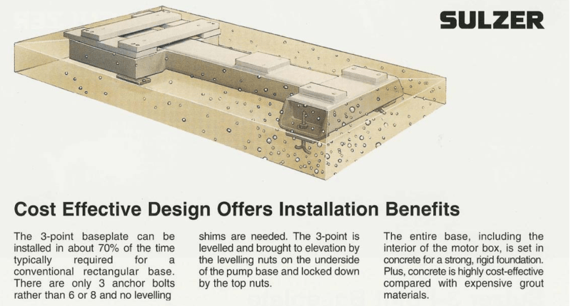
Edit (1/8/2020): The two pumps in use are from Sulzer, and include a T-frame metal base. The procedure for securing the pumps is non-standard (see images below). Leveling/raising the pump is accomplished by washer and nuts on the underside of the base on the foundation bolts. A top nut is used on the foundation bolts to then tighten the entire base down. Then everything is encased in concrete/grout. I've spoken with a Sulzer rep, and he confirmed this procedure. It's odd that this design inherently means there is no tensioning force provided by the foundation bolts, as the top nut is tightened against the bottom leveling nut.

I've read through a previous post from many years ago ( members cautioned against this method. Is that still the case?
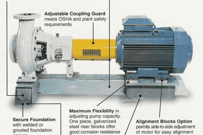
image_r5dyjm.png

image_iqiwrx.png
 
Replies continue below

Recommended for you

BASF is an excellent resource for this. I agree with the procedure you attached. I work in a large oil refinery with about 2000 pumps. We require that all centrifugal pumps are grouted down except for canned motors. We have deviated from that on a few pumps with skid mount bases bolted directly to structural steel. We require epoxy grout for 50 HP and larger. We accept cementitious grout for smaller than 50 HP.

Johnny Pellin
 
JJPellin,

Thank you for that. What about the foundation (concrete, in this case)? Any references you can point me to to evaluate the required mass of the foundation for sufficient vibration dampening? I worked in the TiO2 industry before this plant, so much of those type of evaluations (structural) were handled by subject matter experts or already had existing procedures/requirements that on-site contractors held to as a matter of course. I now am having to cover the all areas project design, and am finding many gaps in my own knowledge base.

Also, a follow-up question. I have no software or experience with flex analysis for piping systems that may place a strain on the pump casing. 100 HP pump is part of a skid unit and straight piped (but not mounted on the skid), but other pumps as part of this system are completely free standing. Contractor's solution to reduce strain on the pump was suction and discharge SS braided flex connections. Thoughts on this? I contended that we shouldn't be using flex connections to compensate for sloppy installation or design, but don't have any way to determine if piping stresses are acceptable from a pump perspective on alignment and the like.

Any advice would be most welcome.
 
To be honest I would do it (grout it in) for any pump more than about 5HP.

The issue is that when bolting down the bots become point loads on the base plate.

I would bet significant money that if you look up the pump suppliers installation guide they tell you to grout the base plate in. And then when your pump fails they will point to the lack of conformity with their installation guidelines and refuse to repair anything at their cost.

In my very junior years I once was responsible for installing a 15kW new uprated pump. No one told me that it needed to be aligned after it had been tested and I assumed that it was all done at the factory and all you needed to do was bolt the thing down and attach pipes and cables. Of course I didn't see / read the instalation manual until afterwards.....

When running it for the first time the supervisor remarked on the high noise and strange smell.

One we had completed the first loading of a tanker, we then removed the coupling guard to find liquid coupling oozing out of the flexi plate. And one of the pump feet was broken.

Cost double the cost of the pump to get the thing repaired and realigned.

So 100HP unit shouldn't be messed with. Fail to get this solidly grouted and mounted and properly aligned with proper guages and checking X, y and angular clearance after fitting the pipework and your coupling and seals will be lucky to last a day or two. If you're unlucky you can wreck the bearings of the motor and pump.

JJP as always offers sound advise and knows much more than I do about pumps in a plant.

Trust your instincts.


Remember - More details = better answers
Also: If you get a response it's polite to respond to it.
 
We require that the foundation block under a centrifugal pump has a minimum mass ratio of three times the mass of the machinery installed on it. We do not normally allow flex lines in our pump piping. But, we are an oil refinery with many streams that are extremely hazardous from a vapor cloud, auto-ignition standpoint.

You did not describe the service your pump is in. For relatively cold service, proper piping alignment and support are probably good enough. The first rigid support on each line should be fairly close to the pump and configured to direct thermal growth away from the pump. The piping should be aligned well enough that you can break the flanges loose and move them into alignment with your bare hands well enough to drop in all of the studs. The gap at each flange should be the thickness of the gasket plus or minus 1/16 inch. When the flanges are bolted to the pump, the coupling hub on the pump should not move more than 0.005" in either the vertical or horizontal. We actually limit this movement to 0.002" in either direction, but that is a very hard standard to achieve.

If you have a high temperature service with a lot of potential thermal growth, you can design the piping with appropriate flexibility using good design practices and will probably be fine for most applications. If you really need to know the thermally induced pipe strain, you can hire someone to perform the analysis for you.

Johnny Pellin
 
Sorry, didn't describe the process conditions. No, not high temp service. Process ranges from 60-120 F. Pressures range from 15-95 psig, so all 150# class piping. Flanges are lap-joint flanges, so no need to worry about torsional stresses. The free-standing pump (15 HP) is piped (straight line) to a 4" fiberglass tank outlet - there are no bends to accommodate thermal growth or absorb pump kick on startup - thus the flex connection. Slightly worried about that nozzle on the fiberglass tank due to that. Pumped material is waste acrylic/styrene acrylic polymers, 0-35% solids, 0-15 cP typical (but going up to 350 cP during one run). Non-haz service. Leaks are in secondary containment and are not a safety concern. System is run as semi-batch, running for ~4 days at a time, then several startup cycles during cleaning before another batch.

Thank you both for the quick and helpful responses!
 
" Slightly worried about that nozzle on the fiberglass tank " .

I think that deserves some serious attention. I //think// this is the 15 HP pump.

You mention 15 HP and 100 HP pumps.
I am unclear as to which is which.
 
Tmoose:

The 15 HP pump is the one that is connected to the 4" fiberglass tank. Another feed line joins the suction line about 6' before the pump and the pipe upsizes to 6" (4 x 4 x 6 tee). There is a 6" SS braided flex on the suction flange of the pump.
 
For these smaller centrifugal pumps, say a 50 hp 1200 rpm machine weighing 2400 lbs on a base approximately 5.7'x2.5', has anyone built a mounting pad/block doweled onto pavement approximately 6" thick using hilti HIT 200R anchor system. This is assuming you can get the 3 times mass with the combination of existing paving, new block and grouted pump base. I've done several larger pumps where we would never consider this and they were on independent blocks. This is the first small pump I've done and it seems like a composite structure with paving, block and grouted base may be an option and save on demolition. This is in an industrial plant, pulp and paper mill.
 
Flex connections aren't meant to allow for sloppy piping. They provide a multitude of benefits including vibration isolation, thermal expansion compensation, AND improve serviceability. I emphasize the last one because I work on the service side of things. Even then, flex connections require engineering. There are additional support requirements for the piping. I like to install 90 bends near components that require service, this allows easy removal of piping sections to provide access to components. I would generally prefer rubber type flex joints for low temp (<150°F) water based applications. I think you'll find the rubber type flex joints are quite expensive and that would be one reason installers may avoid using them.
 
Some of my clients have a lot of these Sulzer pumps on those bases. My recommendation is to follow the Sulzer recommendations as you have shown. These mills here have about 200 of these pumps, ranging from 5 hp to 400 hp, and they seem to have great success with following those steps.

Personally, I dislike those bases, they don't look like much compared to a typical pump base, yet they do work, so I can't argue.
 
I just want to remind some critical points for grouting of vibrating machinery for more than 50 HP..

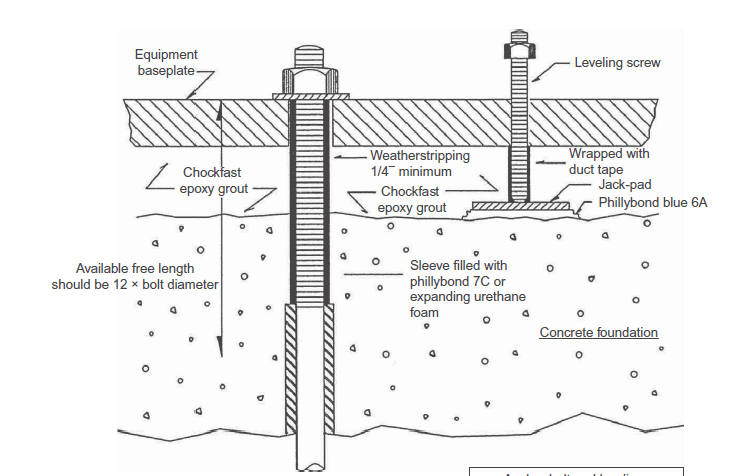
i =The grout shall support the equipment skid. The use of plate shims for adjustment will hinder this concept.

İİ=The use of adjustment nut underside the baseplate for levelling purpose , is not a good idea. This will hinder the loading of grout and tightening of the anchor nut will not be effective.

İİİ= The ( pump mass + grout mass + foundation mass ) shall vibrate as a unique mass to minimize the pump vibration effects. In order to justify this, the anchor bolt sahll be preloaded to a level , such that ,the concrete foundation will receive compression stress around tension strength or the preload shall overcome an externally applied cyclic load.

The following picture is copy and paste from the book ;The Grouting Handbook A Step-by-Step Guide for Foundation
Design and Machinery Installation (Donald M. Harrison )

jackscrew_dmeuac.png
 
HTURKAK,

I've read the same thing regarding not using an underside adjustment nut, as it will not allow the pump, grout, and concrete to be pulled together as a monolithic mass. However, the procedure provided by Sulzer is in direct contradiction to that advice. The pump bases have no spots for leveling jack screws, so they use that adjustment nut on the anchor bolt.

I've spoken with the Sulzer rep, and all they said is that their method "should not be a problem". However, their procedure goes against everything I've read about proper foundation support for pumps, so I was seeking clarification from anyone who has used these style bases before.
 

TiCl4 (Chemical),

I looked to the second picture which explains the 3 point baseplate concept. Apparently, the concrete foundation is cast in the stages ; first stage , the footing poured to certain level with anchor bolts then, the pump is installed and levelled using the levelling nuts underside of the pump base and locked down with top nuts. In the second stage concreting , the entire base including the interior of the motor box is set in concrete. In this case, the pump frame embedded in concrete and no need to grout.

Personally, i would prefer conventional frame rather than 3-point base concept.

If you followed this procedure, and provide a reinforcement cage for the whole footing, the pump and concrete footing will be monolithic mass .

TiCl4 (Chemical said:
I recently installed a 100 HP pump in a temporary capacity, and expect to move it within a year to a permanent location.

In this case , before moving to permanent location, the concrete footing shall be demolished or you will need a new base frame ?.

Just for curious, what about the piping? and ..contribution to the vibration?
 
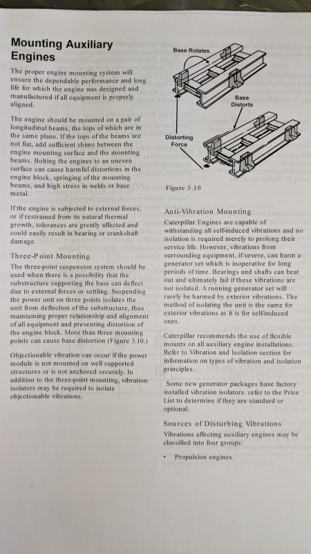
My engine supplier explains the purpose behind 3-point mounting.

IMG_20200708_095858_nznr9x.jpg
 
HTURKAK,

The pump is mounted on a steel frame for the moment rather than being encased in concrete. The piping on the suction and discharge is part of a vendor-supplied system.
 

Your complaint was ,

Aparently, you did not follow manufacturer's recommendation and sound engineering practice.

I will advise you, either follow manuf. recommended procedure ( frame encased in concrete ) or follow conventional method ,provide monolithic mass with preloaded anchor bolts and grout. Otherwise ,the service life of the pump will be adversely affected.

I will suggest you to look API RECOMMENDED PRACTICE 686 and PIP REIE686A.
 
HTURKAK,

HTURKAK said:
you did not follow manufacturer's recommendation and sound engineering practice.

Correct, unfortunately. I advised that a pump of this size would likely experience reduced life, especially seal life, if installed in the temporary location - the nature of the location necessitated a steel frame be constructed rather than making a proper pump base. However, the economics of the temporary installation/operation while the new location was developed meant that this was an acceptable risk to management.

Thank you for the references. I started this thread because I was seeking best practices on grouting requirements and pump foundation design requirements, and I want to make sure the pump foundation is correct for the upcoming re-installation.
 
Steel foundations are perfectly fine for rotating machinery applications. In marine applications everything gets mounted on steel foundations. That includes 120,000 horsepower engines turning 100 rpm to 70,000 hp steam turbines and combining gears operating at 7-10k rpm. Make it stiff enough and use the 3-point mounting and you should have no issues.
 
Status
Not open for further replies.

Part and Inventory Search

Sponsor