Eng-Tips is the largest engineering community on the Internet

Intelligent Work Forums for Engineering Professionals

pump head vs pipe pressure in high rise building 5

Status
Not open for further replies.

carlanox

Mechanical
Nov 8, 2022
9
0
0
ID
Hi all,

I am a new engineer, just started to work. I have a debate regarding the pressure in the chiller closed loop system.
So here is the case:
1. Building height is 110m, as in the vertical pipe height
2. We are using 3 pumps in parallel (2 running and 1 backup) with each pump has 40m head, located in the first floor

So what is the pressure reading on the first floor when
a. no pump is running
b. 1 pump is running
c. 2 pumps are running

and here is what i think.
a. since height is 110m so pressure reading in the bottom is 11 bar, assuming 10m is 1 bar
b. with 40m head pump, the pressure will be 11 bar (gravity) + 4 bar (from the pump head) so total is 15 bar
c. depending on the pump curve, it will be 11 bar + 4 bar + 2 bar assuming 50% for the pump series effect so total will be 17 bar

please advice on my answers. thank you
 
Replies continue below

Recommended for you

I assume you have 1st floor is ground floor?

a and b are correct up to a point. You don't say what your minimum pressure is at the high point / where the expansion tank is.

You normally aim for min 1bar at the highest point to keep the circuit working as a closed circuit.

So a will be 11 plus whatever the min pressure is.
b and c will depend on where your tank is. Usually it's on the pump inlet so would also add whatever the min pressure is.

, but don't understand C. You say the pumps are in parallel? so where does 50% extra head come from?

Also why are they on the ground floor - they are commonly found on the roof / top floor so you don't have such high pressures on your pump.

Remember - More details = better answers
Also: If you get a response it's polite to respond to it.
 
OK, but what pressure does the expanaion tank maintain?

Remember - More details = better answers
Also: If you get a response it's polite to respond to it.
 
Really?

Is this system working or proposed?

Can you draw a schematic?

The length of the pipe from the tank back to the pump would need to be shorter than the feed line. Still trying to work out how this works.

Remember - More details = better answers
Also: If you get a response it's polite to respond to it.
 
Because your atmospheric expansion tank is connected to the top of the loop this is your 'reference point' - the pressure here wont change significantly.

Assuming:
- The 40 m of head refers to the condition achieved when one pump is running as installed in the closed loop
- For the sake of easy numbers, that the pump is located with exactly half of the head loss upstream between the expansion tank connection and the pump suction and half downstream between the pump discharge and the expansion tank
- When two pumps are running in parallel as installed in the system they develop 60 m of head (per your guess)

a) No pumps running: only gravity head so suction head = discharge head = 110 m (11 bar)
b) One pump running: pump develops 40 m of differential head against the system resistance, so the pump discharge head is 110m gravity head plus 20m = 130 m (13 bar), suction head is 110m minus 20m = 90m (9 bar)
c) Two pumps running: similar to above the discharge head is 110 + 30 = 140 m (14 bar) and the suction head is 110 - 30 = 80 m (8 bar)

The above is illustrative of what will happen with an expansion tank connected somewhere in the middle of the closed loop, to get the actual numbers expected you would need the pump curve and a good estimate of total system resistance as well as the split in system resistance from the pump to the expansion tank and from the expansion tank back to the pump.
 
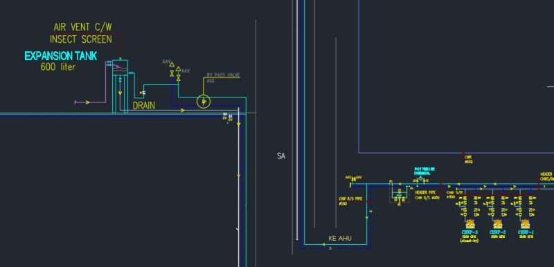
here is the drawings


I combine it to make it for the space. on the right is the pump room located on the first floor. the pipes goes up, up to roof top where the expansion tank is located at the height of 110. 2 pumps are running while 1 is backup. I also removed all the details on each floor where the FCU's are located.

chiller_pz3yqq.jpg
 
I think it's still a bit odd to have an atmospheric tank on this system compared to a pressurised system, but if it works then fair enough, there is no significant additional head other than height of the building.

As GBT says, it impacts the working pressure which is not as high as you had calculated. However if someone closes a valve somewhere on the discharge side then max pressure (shut in) will be around the 15 to 16 bar on the discharge of the pump.

Remember - More details = better answers
Also: If you get a response it's polite to respond to it.
 
For pumps in parallel, the developed heads ARE NOT ADDITIVE. The flow rates are.
With 40m head pumps, it does not matter if you have 4 or 4000 pumps in parallel, it will never reach 110 M of head.
You would have to place the pumps IN SERIES to get the desired head.
 
110 m water column pressure is the all system pressure, with no pump run.
It is a closed loop circuit.
The pump discharge pressure is the developed pressure due to water flowing by circuit resistance by friction trough the pipes, valves, and fancoil units.
if you put one gauge at suction and other at discharge , is no flow, both will be the same, or 110 m water column, when pump run , the suction pressure will drop, and discharge will up, the pressure difference is the pump head pressure.


At the foot of a 110 m building the static head is 11 bar so your answer to question a is right.At the suction inlet of the pump(when stationary) the head is 11bar.So when the pump starts its discharge pressure is 11+4=15 bar so your answer to question b is correct.I am not quite clear on question c.Whether you run 1 or all pumps the discharge pressure still will be 15 bar.

The more important question is what is the purpose of this exercise.Are you trying to check if the piping and fittings are of right pressure class?
 
Sak9.

If this was a true closed circuit then maybe. But at what we assume is a midpoint of the system the pressure is essentially fixed at 0 barg as it is open to atmosphere at the highest point. Hence the inlet pressure to the pump needs to drop to around 9bar, so discharge is around 13.

But yes, don't understand the reason.

Remember - More details = better answers
Also: If you get a response it's polite to respond to it.
 
yes. need to know the pressure to decide on the valve pressure ratings. either use 16 bar rating or 25 bar rating. I am thinking to use 25 bar rating for the first 8 floor and the rest can use 16 bar rating.

regarding the pump in parallel, the head and the flow will increase (I think) depending on the curve.

not sure about not responding to the reply. I think i did?
 
I think your design case is 11 bar at the pump inlet then diff head at no flow to look at the blocked in case. If the running DP is 40m, this is probably no more than 50m, but check the pump curve.

If this is less than 16 bar then I would go for 16 bar rated throughout or if you want a bit of margin 25bar for maybe the first 2 or 3 floors.


Remember - More details = better answers
Also: If you get a response it's polite to respond to it.
 
You will be fine with 16 bar rating.110m-120m is probably on the border of a single stage chilled water system. If you were to go any higher it is more economical to split the system into two stages of lower pressure rating. The weakest point in these type of systems is the AHU coil which I think the max pressure rating is 16 bar.
 
carlanox,

You seem to have been a bit off with your data.

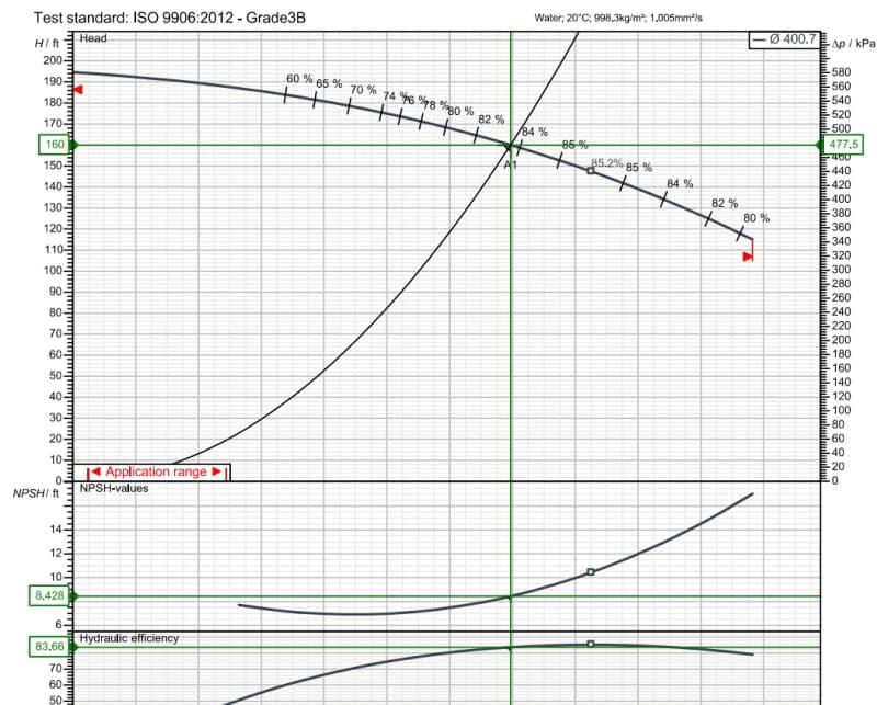
If the green line is your duty point, then at operating condition you're diff head is actually 160ft or as it shows on the other graph, 4.8 bar in water, not 40m.

So your running pressure is prob about 13.5 bar if the tank is in the hydraulic middle point.

But shut in head is 5.8 bar pressure plus the 11 bar in the inlet so 16.8 bar.

Definitely needs the 25 bar flanges for the first 2 or three floors.

But you seem to be right on the limit for a lot of things and I think you risk leaks and burst in the pipework and equipment on the lower floors if you go with this design. you wont' be able to set relief valves that close so you could be looking at having to set them at about 20 bar to avoid them popping off.


Remember - More details = better answers
Also: If you get a response it's polite to respond to it.
 
carlanox said:
I dont know how to quote,

You copy the text you want to quote, press the symbol of the little man with a speech bubble on top of his head at the top of the reply box ( about two to the right of the smily face, type in the name of the person, click Ok then paste the quote where the cursor is ( middle of the ] [ ) then bingo.

No problem. Hope this makes sense now?

Remember - More details = better answers
Also: If you get a response it's polite to respond to it.
 
Status
Not open for further replies.
Back
Top