Continue to Site

Eng-Tips is the largest engineering community on the Internet

Intelligent Work Forums for Engineering Professionals

  • Congratulations IDS on being selected by the Eng-Tips community for having the most helpful posts in the forums last week. Way to Go!

Pump Margin Question 1

Status
Not open for further replies.

MrProjectEng

Mechanical
Nov 10, 2016
40

Hello;
I would like to increase pump safety margin gap without changing impeller or etc.
What can be done?
By the way, what is relation between pump suction and discharge pressure and margin. I have 52 Hz 35 bar, 55 Hz 38 Bar but 47 Hz 2,2 Bar discharge pressure, how can be increased at 47 Hz discharge pressure.
 
Replies continue below

Recommended for you

You have not provided enough information for me to understand your concern. What safety margin are you concerned about? What service is the pump in? What type of pump are you using?
The data you provide tends to suggest a variable speed, motor driven pump of some sort. But, I have no idea what type of pump this is or what margin you are concerned about.

Johnny Pellin
 

Thank for your reply.

1)Centrifugal pump will be used as condensate pump that pump in Cold Water (density= 1000 kg/m^3). My concern is about 47 Hz 2.2 bar pressure. I'd like to increase this value. Is there any way...

2)On the other hand asking what is the relation between frequency and pressure for all centrifugal pumps. I consider that if frequency increases shut off head increases as well. Right??

 
2.2 bar at 47Hz doesn't make any sense without an explanation as to the reason why.
The relationship of frequency and head is (Hz1/Hz2)^2

It is a capital mistake to theorise before one has data. Insensibly one begins to twist facts to suit theories, instead of theories to suit facts. (Sherlock Holmes - A Scandal in Bohemia.)
 
You have still not told us what you mean by margin or safety margin gap. A centrifugal pump will operate at the intersection of the pump curve and the system curve. The pump curve will change based on speed as Artisi has noted above. You have told us nothing about your system. Now, you mention shut off head. Are the pressures you have listed shut off pressures?

You surely can't expect us to give you meaningful advice with so little information provided.

Johnny Pellin


I realize that... I am fresh on pumping Tech. I am struggling to get that. I've just told about margin which means head and flow margin...The pump must have wide frequency gap.

Firstly I would like to ask relation between frequency and pressure.
I consider that increasing frequency causes incereasing head margin??
At the same time if frequency increasing what happen to the shut off head?

I hope being more clear...

Thak you for your reply.
 
The influence of frequency change was explained earlier - increase Hz increases head / pressure at the square of speed change, or reduce for reduced Hz - nothing to do with margins.
We currently know nothing - this means we can't assist. Take some time and fully document what you are trying to do / achieve.

It is a capital mistake to theorise before one has data. Insensibly one begins to twist facts to suit theories, instead of theories to suit facts. (Sherlock Holmes - A Scandal in Bohemia.)
 
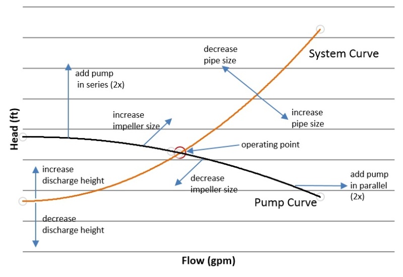
As mentioned earlier, a particular pump with certain impeller will operate on the intersection of the pump curve and system curve. You can change the operating point by either changing the pump or the system.

Change the pump curve by changing impeller, speed or adding pump.
Change the system curve by increasing pipe diameter, removing fittings, or lowering discharge height.

pump_system_curve2_qbzaot.jpg


To quantify the changes see pump affinity laws.

I used to count sand. Now I don't count at all.
 
You're not being very clear at all, but language or translation might have something to do with it.

The 47 htz figure you provide does not make sense. compared to the other two data points which indicates that there is something wrong with the reading or your data.

If you want more help you will need to provide details of your pump and system and your pump curve.

As noted by sand counter the curve shown moves up for increased frequency / speed and down for reduced frequency / speed. So the shut foo value moves at the same time.

Remember - More details = better answers
Also: If you get a response it's polite to respond to it.
 
Adding extra capacity (if that is what you are labeling "increase pump safety margin gap") is generally a bad idea. Oversizing pumps will waste a lot of money over the long term.

You should address the operating scenario first to determine the ideal pumping scheme.
 
I always prefer to size to the right of the BEP and select the impeller in the middle of the available sizes. When sizing, intuition says to add safety factor on to the head, but in reality, safety factor should be put on available power.

I used to count sand. Now I don't count at all.
 
SandCounter : I would suggest it is better to select slightly left of BEP so any increase in flow doesn't run further out on the HQ curve.


It is a capital mistake to theorise before one has data. Insensibly one begins to twist facts to suit theories, instead of theories to suit facts. (Sherlock Holmes - A Scandal in Bohemia.)
 
In my experience, it is flow that is the stated requirement when designing a system. Head may be specified, but it is a necessary evil. I've never seen a centrifugal pump application where head was tghe objective and flow was the byproduct.

Usually there ends up being some design compromises in the final as-built system. Whether it's routing pipe around obstructions, added fittings, or generally inefficient routing, this all adds head. Once you have the system built and discover that your pump won't make the flow, if you've designed to the left of BEP, it's expensive to change the pump and changing impeller diametrr has little effect on flow. However, if something crazy happens and you actually have less restriction and the pump has a tendency to run out, you can easily throttle a valve or add an orifice.

Another advantage to designing to the right of BEP is that the pump curve is much steeper so change in head has less effect on the flow. On the left side of BEP, the shallow slope of the curve means any bit of unexpected head will yield severe change in flow.

I used to count sand. Now I don't count at all.
 
SandCounter: I feel I need to comment on some points you have made:
1. Static head for any system is set, however total head is a function of design, therefore it is not a byproduct of the overall system but an integral part having a major influence on good pump selection.
2. In my experience - I would say that usually, total head is over stated or over calculated for many reasons - but that's another discussion.
3.hopefully you are not discussing high power units of 100's if not 1000's Kw when you refer to throttling valves or orifice plates to control over capacity.
4.Saying curves are always steeper left of BEP is a nonsense generalization.
5. Cannot see the logic is selecting a pump to run right of BEP based on the above.
6. Depending on how far right of BEP the following problems are encountered, increased NPSHr - possible cavitation, mismatch of flow into the impeller eye, vibration, shaft deflection, mechanical seal problems etc. of course operation too far left of BEP brings its own problems.
7. Sound engineering based on correct hydraulic knowledge, discussions with the operator / owner, reviewing what is actually required now as well as in the future can usually lead to an accurate / good pump selection.

A good pump selection (assuming the correct pump style / materials are selected) should be based on - efficiency, NPSHa/r, lowest possible speed and of course being able to achieve the desired flow at head imposed on the pump.


It is a capital mistake to theorise before one has data. Insensibly one begins to twist facts to suit theories, instead of theories to suit facts. (Sherlock Holmes - A Scandal in Bohemia.)
 
Select the pump for the design gpm but plus 15% pressure head. Note also pipe friction loss difference between open system and closed system per Carrier pipe friction charts.
 
Artist, below I respond to your numbered comments. Our differences probably represent differences in both experience and design philosophy.

1. Head is an integral part, yes, but I have never seen it as the objective. It is an effect of flow.
2. In my experience - head is understated, but it shouldn't matter if you put your safety factor on the available power rather than the head.
3. I have successfully designed this way for systems with single and multiple pumps in excess of 5000 HP and have applied orifice plates or discharge baffles to control over capacity when the installed system deviated from the plans or pump was repurposed from another system (which is the majority of my experience).
4. Can you give an example of a centrifugal pump that does not follow a quadratic curve that goes from high head/low flow to low head/high flow? This would be unique in my experience.
5. -
6.I'm talking just to the right. If you're still on manufacturer's curve, and not extrapolating, you should be fine. Of course you check NPSH, but you would do that anyway.
7. This is where we probably have the greatest difference. Getting a hold of real "knowns" including actual static lift, viscosity, actual pipe length, fitting count, and sometimes even SG in the 5 minutes to a half an hour I normally have to select a pump is a pipe dream. Designing to the right of BEP along with some educated guesses has helped me to consistently select for robust systems which have rarely needed rework, and when they have, its limited to impellers or orifices. Always have a plan B.

I might note also, that selecting a pump per Lilliput1's comment, design for head + 15% will put the actual operating point to the right of BEP so long as "design for" means for best efficiency.


I used to count sand. Now I don't count at all.
 
SandCounter,
Guess we could discuss this back and forth for ever point by point and not really achieve all that much at the end of the day, however, my initial response was really to highlight for anyone reading this post that there was an alternate argument to what is "correct" or "best" selection - a second opinion.
Just a couple of points on your reply, the curve you posted earlier I would think is fairly typical of most pumps, it shows a fairly constant rise from run-out upto CV not much steeper either side of BEP (wherever it might be on that sketch)and secondly, throttling large pumps wastes enormous amounts of energy and not something I would ever recommend other than short term giving time to evaluate an over flow or head installation.
For interest, I haven't been involved in a pump selection along with all the usual problems / unknowns for over 15 years - and guess what - I don't miss it [wink].


It is a capital mistake to theorise before one has data. Insensibly one begins to twist facts to suit theories, instead of theories to suit facts. (Sherlock Holmes - A Scandal in Bohemia.)
 
Status
Not open for further replies.

Part and Inventory Search

Sponsor