Continue to Site

Eng-Tips is the largest engineering community on the Internet

Intelligent Work Forums for Engineering Professionals

  • Congratulations GregLocock on being selected by the Eng-Tips community for having the most helpful posts in the forums last week. Way to Go!

pump reaction to load 5

Status
Not open for further replies.

saeedplc

Electrical
Nov 27, 2021
126
Dear Experts,

Could you please let me know what happens to a centrifugal pump if the load (e.g.fan coil or any other thing that take flow from the pump) connected to it is in two cases
less and higher than the pump specifications?
what is reaction of the pump in the two scenario?

Thanks,
 
Replies continue below

Recommended for you

The allowable pump nozzle loads are about keeping the pipe aligned with the motor, and this depends on the stiffness of the base.
 
Centrifugal pumps create flow and will operate on the pump performance curve at an operating point. As the resistance to flow changes (load), the centrifugal pump operating point will change to a different operating point on the pump performance curve.

If the difference in flow is far off from the design operating point, the centrifugal pump may be damaged by operating off the design curve. You should consult with the pump manufacturer. It may be possible to change the pump impeller size to match the changed pump conditions.
 
Sorry for poor outlining the question
I edited the question
 
The operating pressure will change. See the pump curve. It shows head/pressure at each flow rate.

A black swan to a turkey is a white swan to the butcher ... and to Boeing.
 
Thank you all so much for the replies

I mean assume the load connected to the pump is drawing a specific flow but the pressure created in not intersecting the pump curve now what will happen?
To be honest i can not work out an operating point that is not crossing the pump curve.
Please consider the pump is in a close loop.
 
The pump wants to give maximum pressure at low flows. At maximum flow, it will have no or very little pressure.

The pipe and rest of the system connected to it want to do the opposite. At max flow, it will need max pressure. At low flow it won't need so much pressure. If the flow rate you want is higher than the pump capacity, you will have no pressure.

When you connect pump and piping together, they will fight it out until they reach a compromise at the operating point. The pump makes pressure at a flow rate that can pass through the system. If it's not what you want, you will have to control it somehow, or make some changes to the pump, system or both.

More than that I cannot say without knowing all the system and pump details.


A black swan to a turkey is a white swan to the butcher ... and to Boeing.
 
I believe a review of Centrifugal Pump curves and operating points is in order here


Could you post more specific details about your pump and system ?

Can you post engineering drawings, photos, performance curves etc ???

More information equals better answers !!!!


MJCronin
Sr. Process Engineer
 
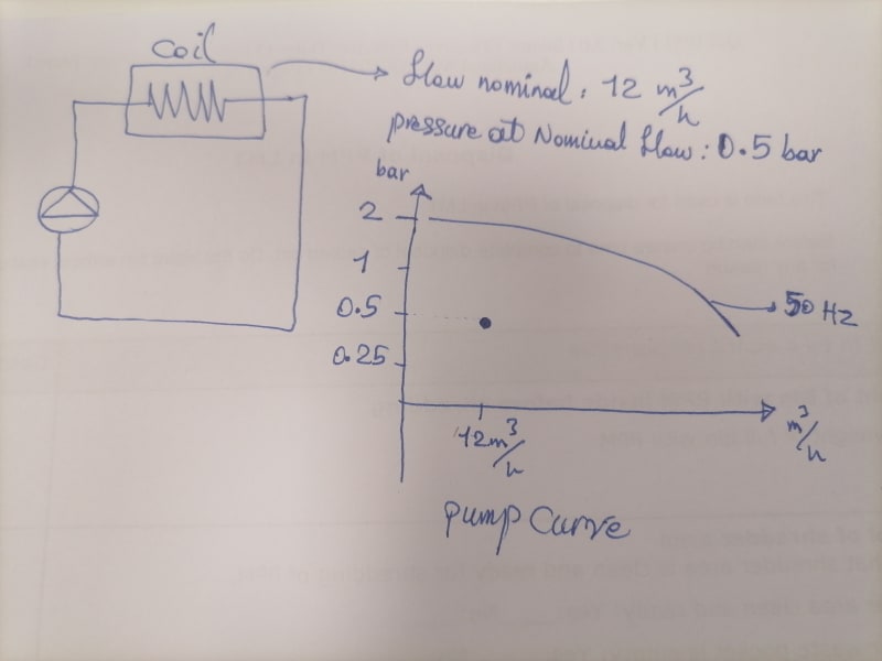
1653839747322_qb1bnw.jpg


There is no real system I put forwardvthe question only out of curiosity so please have a look at the above photo and let me know how the pump and coil reach to a compromise and what will hapoen to the coil and the pump?

Thanks a lot
 
The "compromise point" is called the "operating point" and is always found somewhere on the pump curve.

That pump will give you about 2barg pressure at a flow rate of 12 m3/h
Find your flow rate and move up on the graph until you hit the curve. That's what the pump wants to do at 12 m3/h. 2 barg.

But that's only half the problem solved. The coil and piping system also have a curve. You must construct that curve. Start with a pressure of 2 bars at the pip/pump discharge and find the flow rate that will pass through the pipe and coil. If that flow rate is 20 m3/h, the pump will try to give you 20m3/h, but the pressure will drop to 0.5 barg. Find the flow through the equipment at 0.5 barg. If it is less than 20 m3/h, Say 15 m3/h, than that's the new flow. Check the pump pressure at 15m3/h. Maybe that's 1.5 barg. Check the pipe and coil again at 1.5 barg. If 15 m3/h will pass through at 1.5 barg, then that will be the operating point. You're done. If not, keep on going back and forth, pump and system, system and pump until you find out where pump pressure and flow equals the flow and pressure in the system. That's the operating point.

You can do it all at the same time. Start a list of system inlet pressure and system flow values.
From pressure 0 to 2 bars, incrementing by 0.25 barg each line. At 0 pressure, you have 0 flow through the system. At 0.25 barg you might have 5m3/h flow through the pipe and coil. At 0.5 barg, maybe you have 10 m3/h flow. .... at 1.5 barg, maybe you have 15 m3/h flow. At 2 barg, maybe 20 m3/h goes through the system. Now plot that list on the pump curve graph. Where the two curves cross is the operating point.

If they don't cross, you must find a different pump, or run it faster, etc.

A black swan to a turkey is a white swan to the butcher ... and to Boeing.
 
The coil does not 'draw' a particular flow as you are posing the system. What you have illustrated is one point on the system curve. The system curve will have many of those pressure at flow points, as does the pump. If that one system data point is not on the pump curve, the pump flow will adjust until a common operating point of flow and pressure is reached.

Ted
 
You have two options here in you example.

You can let the pump and its load find the point in the pump curve where the differential pressure in the loop matches the pump DP at a certain flowrate. The thing you haven't mentioned is whether the pressure differential at a certain flow is for the coil only or the coil AND the piping. I assume only the coil.

So depending on the frictional losses in the pipework, the actual flow may be more or less than 12m3/hr.

If you actually only want 12m3/hr and the frictional losses are <1.5 bar then you need to introduce more frictional losses by using a control valve.

Remember - More details = better answers
Also: If you get a response it's polite to respond to it.
 
No sense in reading or trying to understand the documents that I posted ...... No siree !!! .... Too much work !!!

Much easier asking and repeating the same question over and over again requiring kind strangers to repeat themselves ...

MJCronin
Sr. Process Engineer
 
There are two curves, a system curve that describes the pressure drop vs flow for the system and the pump curve.
Where the two intersect will be the operating point, period.
No exceptions and no options.
Go back to MJC's references, they explain this well.

= = = = = = = = = = = = = = = = = = = =
P.E. Metallurgy, consulting work welcomed
 
pierreick ....

He is not gonna read it ..... Nope, wayyyyyyyy too busy !!!

Can you pre-digest it for him ?

MJCronin
Sr. Process Engineer
 
Status
Not open for further replies.

Part and Inventory Search

Sponsor