Continue to Site

Eng-Tips is the largest engineering community on the Internet

Intelligent Work Forums for Engineering Professionals

  • Congratulations GregLocock on being selected by the Eng-Tips community for having the most helpful posts in the forums last week. Way to Go!

Pump station grounding system 2

Status
Not open for further replies.

Sdhaytham

Electrical
Nov 10, 2009
4
Hi guys ,I need some help on what a suitable grounding system for pump station with two source a delta/wye transformer as main and a standby generator , most of genset in my area is coming with grounded neutral point bonded to the gen body ,and the transformers grounded solidly at wye side, as a common habit we used to use (RH99)relay for residual earthing current protection installed in both MCC and MDB panels ,before writing here I have checked Schneider 143 white paper and ieee green book but I come out with nothing ,
I appreciate if there is any technical analysis for for my case

 
Replies continue below

Recommended for you

Howdy Sid,
Need some additional information;
1) What voltages are present? (include Incoming Utility and Utilization Voltages)
2) Is the (step-down) transformation supplied by the Utility (or is it Owner supplied)?
3) What is the size of the power system? (ie xfmr size, generator size, pump size)
4) Why are the neutrals not resistance grounded? (ie If you do not have any line-neutral loads then a NGR is highly recommended).

Depending on the answers to 1) and 2) above are; you could end up designing a ground system that must control touch-and-step potentials.
GG


"I have not failed. I've just found 10,000 ways that won't work." Thomas Alva Edison (1847-1931)

 
Thanks groovyGuy :)
1. The system 380 volt ,feeded by 1.5 MVA 11/0.38 kv delta/wye transformer supplied by utility ,standby gen is 1 MVA , both source connected to the load through a 3 poles ATS unit .
2. we installed ( Identical 5#pump/motor 220 KW,soft starter control .
There is a line - neutral load that why the transfomer is D/Wye grounded solidly at secandry side (wye) using (TN-S) or (TN-C-S) arrangement recommended by utility contractor.
 
As it appears to be too late to install a 4-pole transfer switch, consider placing the main neutral-earth bond at the switchboard and not at the transformer / generator. Might not be an option if the transformer is a utility-owned asset rather than in your ownership.
 
If the generator is fairly close, I would run a chassis ground to the gen set from the main panel. Connect the general neutral to the neutral bus in the main panel.
If the generator is some distance away it is often safer to connect the generator neutral to the chassis ground at the generator.
More than one connection between the neutral and ground makes ground fault detection more challenging.

Bill
--------------------
"Why not the best?"
Jimmy Carter
 
Thanks guys for your helpful resposes ..
Scotty:yes its not an option to cancel groundinng at the transformer but you have the right to bond the neutral system or not ,as grounding sys has been arranged. common or separated neutral .
Waross:I already arranged as you mentioned connecting the gen frame to the main bus and the hole sys is tn-s.
My question is if I added more rods distributed and connected together make it as a net to minimize the total ground resistance ,does it works , as it's clear a multi leakage current loops has been made.

Thanx again
 
Bill, you are not afraid of challenges - are you?

Serious: I hear about ground loops and how bad they are. Quite often.
But I cannot see any real reason (except in some audio installation where "hum" may be a problem) that there's a true reason to avoid them.

A mesh/grid is actually a ground plane with holes in it and, as such, a much better alternative than a tree. I have quite a few cases where the tree has caused severe potential differences and damages to bearings and where a mesh has reduced the risk considerably.

Gunnar Englund
--------------------------------------
Half full - Half empty? I don't mind. It's what in it that counts.
 
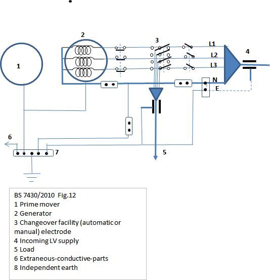
In my opinion, you can follow the BS7430/2010 :
ch.7.2.5 Generators providing a changeover supply
Figure 12 Single low voltage standby generator (without paralleling facility)
NOTE Changeover switch could be 3-pole with linked neutral.
and ch. 7.2.7 Generator operating in parallel with the electricity supply
Problems of neutral/earth circulating currents arise when a generating set is operated in parallel with an incoming supply; where the magnitude of the circulating currents would be excessive or if the generating set is also required to operate in the changeover mode, the options described in 7.2.6 should be followed.

BS7630_Fig_12_umoqx5.jpg
 
The neutral must only be connected to ground at one point. The utility side of your transformer is on them but the low voltage side of the transformer should have a 5-conductor cables (or 4 conductors and metal conduit). The chassis of your generator, transformer, and switchboard all need to be bonded together. The neutral will come into the switchboard from the transformer and generator as its own wire where they will combine on the neutral bus. This is where a jumper should be made to the ground bus and you should install your current transformer to measure leakage current.

If none of this is practical, isolate the neutrals in the generator and transformer and install an additional transformer to drive your lower voltage loads. I find 30-45kva transformers to be quite inexpensive to provide power for lighting and such vs reconfiguring an incorrectly wired system (lots of people pull 4 conductor cables instead of 5 in my industry).

You can leave the ground connected to the neutral in the transformer as long as you don't have any additional ground connections anywhere else. You current transformer for your fault detection will be placed in thr transformer in this case.
 
The neutral must only be connected to ground at one point. The utility side of your transformer is on them but the low voltage side of the transformer should have a 5-conductor cables (or 4 conductors and metal conduit). The chassis of your generator, transformer, and switchboard all need to be bonded together. The neutral will come into the switchboard from the transformer and generator as its own wire where they will combine on the neutral bus. This is where a jumper should be made to the ground bus and you should install your current transformer to measure leakage current.
I guess you pointed to TN-S arrangement , that what finally after long searching and of caurse guys with your help and directions to the right code points I think tn.s arrangement is the suitable to the case .
Thanks everyone for the great help

Sharshar
M.east
 
Under some codes, you must ground the neutral in the main panel in addition to the utility ground at the supply transformer.
In that case you must check the residual current on all three phase wires plus the neutral.

Some comments on grounding and bonding.
Grounding/bonding serves more than one purpose.
In solidly grounded systems, the bonding of equipment and the equipment grounding conductor is to ensure that in the event of a ground fault enough current is drawn to trip the breaker in a timely manner.
The other purpose is to prevent touch voltages from appearing on the surface of the equipment.
One ground may not always serve both purposes.
Consider a motor on a long cable. The motor is grounded by the grounding conductor in the cable.
The motor is near a grounded surface but is not bonded to the surface.
In the event of a ground fault in the motor the current path will be out on the phase conductor and back on the grounding conductor.
The conductors in the cable will form a voltage divider. On a 277:480 Volt system the voltage on the motor case may rise to 277/2=139 Volts until the breaker clears.
There will be 139+ Volts between the motor frame and the nearby grounded surface.
(Typically the grounding conductor is a smaller diameter than the phase conductor. As a result the voltage drop across the grounding conductor will be greater than the voltage drop across the phase conductor. A purely resistive solution would show the voltage at the motor to be quite a bit higher than one half of the 277 Volts. However the impedance is not purely resistive and inductive reactance will tend to lower the voltage on the motor frame. The voltage to ground on the motor frame will still be greater than 139 Volts.)
The issue touch voltages on the motor frame may be dealt with by grounding the motor locally so that the motor frame is at the same potential as the surrounding surfaces. As well as being connected to the motor frame the surrounding surfaces may be connected to local grounding electrodes or, if available, the main grounding grid.
In the areas that I am familiar with, the code requires that the motor be grounded back to the supply.
In addition to the code requirements, all the petro-chemical plants that I have worked at in the last 30+ years connect a second heavier ground conductor from the motor frame to the local ground. A motor fed by #12 AWG phase conductors may be connected to the local ground by a #2 AWG conductor.

Bill
--------------------
"Why not the best?"
Jimmy Carter
 
The golden rule and which is documented in my regulation book is that your neutral should only be earth at the star point of your source
so if you have two sources you will have to use a four pole change over so that you are only using one star point
 
Status
Not open for further replies.

Part and Inventory Search

Sponsor