Eng-Tips is the largest engineering community on the Internet

Intelligent Work Forums for Engineering Professionals

Pump Suction Pressure

Status
Not open for further replies.

p6g2p6

Mechanical
Jul 28, 2021
33
0
0
CA
Hi,
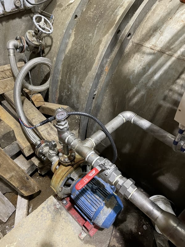
At one of our plants, we have a booster pump for a cooling water system. It draws water from the penstock, which according to the transducer has a pressure of 21 PSIG. The suction-side piping stems right off the penstock then there is a ~5ft 2" hose that connects to the pump. There is a pressure gauge on the suction side and that was reading 30 PSIG, therefore 9 PSI higher than the penstock pressure. The transducer for the penstock pressure is placed at the same elevation as the pump. Is it normal for the suction pressure to increase when a pump is drawing from a source that has a greater pressure than atmospheric? Or is there a good case that either the gauge or transducer reading is incorrect?
Thanks in advance!
 
Replies continue below

Recommended for you

Yes there is a very good case for one or the other being incorrect otherwise you've just discovered free energy for life....

Remember - More details = better answers
Also: If you get a response it's polite to respond to it.
 
LittleInch, I'm going to be rich! Just kidding thank you. I figured that was the case, just wanted to make sure that I wasn't missing something.
 
We used to fight with this all of the time.
One issue is how the gages are plumbed in.
If they are on a small diameter "T" off of a large pipe, are in a location with lots of turbulence, or if there is ever a chance of air in the system then you can have other issues as well creating what looks like a deltaP.
We had one system where we made the operators shut down all of the pumps on the last workday of each month and then record the pressures.
There was some system head because of a holding tank.
If they could read a difference the work orders were entered.
And the gages in the locations with turbulence didn't last long in spite of using good dampeners.

= = = = = = = = = = = = = = = = = = = =
P.E. Metallurgy, consulting work welcomed
 
Could also just be different velocities. Venturi effect. In connected pipes of different diameters, a slower flow velocity will read a higher pressure. A faster flow velocity will read lower pressure. Elevations being equal.

--Einstein gave the same test to students every year. When asked why he would do something like that, "Because the answers had changed."
 
I came across a similar problem many moons ago - the inlet pressure reading in operation was way over the actual static head on the pump inlet - after much head scratching and gauge change it turns out the pump was pre-rotating the inlet flow which in turn was seems as a pressure increase, installed a flow straightener prior to the pump inlet flange - problem solved.

It is a capital mistake to theorise before one has data. Insensibly one begins to twist facts to suit theories, instead of theories to suit facts. (Sherlock Holmes - A Scandal in Bohemia.)
 
I was a bit fast to assume things. The actual take off and location of the pressure take off and proximity to the pump are crucial.

Any drawings or photos of the two take offs?

Remember - More details = better answers
Also: If you get a response it's polite to respond to it.
 
Thanks all for the great insight. See photo below of pump and piping off the penstock. I think I'll start with replacing the gauge first to see if its just a simple fix. If that doesn't resolve the issue then I may need to try a flow straightener or rearranging piping. Yes, I know the steel hose is too long - we were in a pinch, but it will be replaced soon with the appropriate length. If it is due to the venturi effect as 1503-44 mentioned - is there a way to get around this?
IMG_1700_ewfxr0.jpg
 
Jesus they are small gauges.

Yes the pump suction one is far too close to the pump to get a reliable reading and there may be something going on with swirl in that bit of pipe.

Also curiosity - what is the tab on that flange just upstream from the gauge?? That often signifies an orifice plate or something other than a gasket??

One thing to check - were they all zeroed for altitude? Many have limit stops so the one reading low could be reading negative at atmospheric pressure.

Or the one reading high reads 9 psi at atmospheric pressure???

Remember - More details = better answers
Also: If you get a response it's polite to respond to it.
 
LittleInch, I wasn't around during original construction and its not shown in the drawing, however I do believe that it is an orifice plate between those two flanges.

Yes, they were all zeroed for altitude. I'll have to get that gauge relocated to see if that fixes the problem.
 
I really don't understand why anyone would install an orifice plate there, but that could easily be doing something very strange to your readings.

While you're at it to move the gauge, try removing the orifice plate as well. You might find the pump works better....

Remember - More details = better answers
Also: If you get a response it's polite to respond to it.
 
Could be doing strange things to the pump also.
I hate to see any inlet restriction on a pump.

= = = = = = = = = = = = = = = = = = = =
P.E. Metallurgy, consulting work welcomed
 
That thing between the flanges could be a temporary strainer.

The gauges probably aren't all that accurate if you're reading down at 20-25% of full scale.
 
Still needs to go though if its not marked on any drawings. Can't see a filter / strainer being pressed between two flanges though?

But yes, a bit of calibration would be interesting to see but these are very small gauges.

Remember - More details = better answers
Also: If you get a response it's polite to respond to it.
 
It seems as if inserted piece in upstream flange is neither orifice nor strainer. May be guage or transducer problem. Try to fix suction piping with rigid support because it can cause vibration, alignment and bearing pre-mature failure issues.

Daren!
 
Hi,
Dismantle the suction line and use proper piping, piping support, etc. You should have a strainer at the inlet of the pump.
To me, what you call an orifice looks like a temporary strainer (conical shape) used at the start-up of a new unit to collect dirt. This is the reason why you have a flexible hose to ease the task.
Too much talk. Poor design and maintenance of the existing unit.
My 2 cents
Breizh
 
Correct, too much talk - considering the question was about suction pressure, not inlet pipe, strainers, maintenance, oriface plates etc., sure installation may not be be ideal - but as usual there is half a story, is the pump performing in accordance with design or is it not.

It is a capital mistake to theorise before one has data. Insensibly one begins to twist facts to suit theories, instead of theories to suit facts. (Sherlock Holmes - A Scandal in Bohemia.)
 
Status
Not open for further replies.
Back
Top