Eng-Tips is the largest engineering community on the Internet

Intelligent Work Forums for Engineering Professionals

PV Panel Repair 4

Status
Not open for further replies.

Sparweb

Aerospace
May 21, 2003
5,103
0
36
CA
A friend and I were messing about with some defective PV Panels over the weekend. We opened the junction box and removed the silicone potting to see what we could do about them.
Once enough potting was removed, we found that we could re-solder the tabs and replace the diodes.
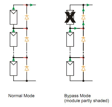
Since this is a little out of my discipline, I'd like to confirm that my choice of Schottky diode was suitable:
Schottky Barrier Rectifier DST2045AX, 20A, 45V
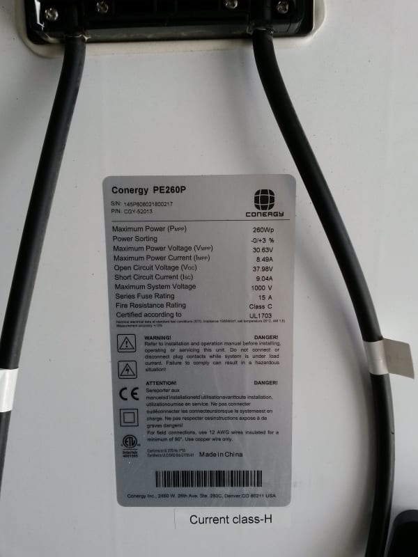
The panel specs are as follows:
Panel_Label_resize2_uw13on.jpg


The replacement bypass diodes looked like this:

Panel_Box_Diodes_Replaced_resized_dhp4k7.jpg


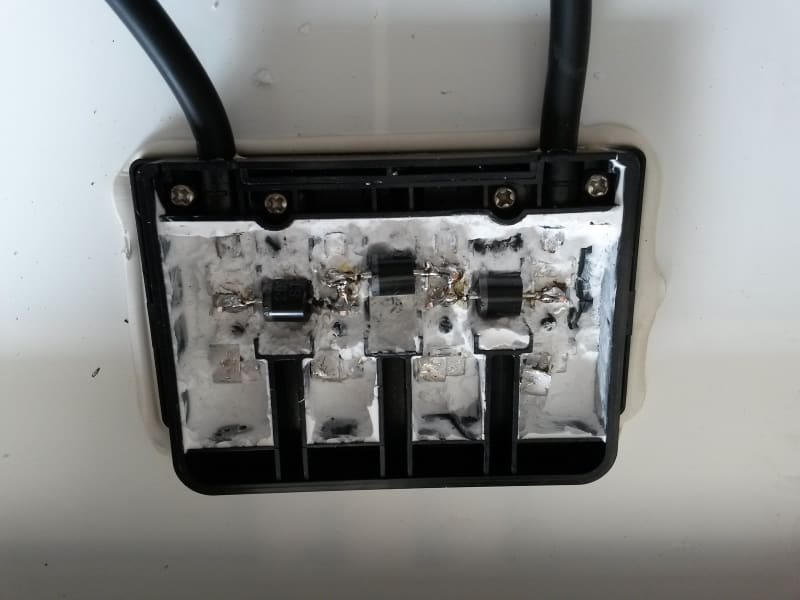
You will also note that one of the tabs is broken. That was fixed after the picture was taken.

Panel output in the available sun was 34.6V open-circuit. Short circuit was ~7 amps. When connected to resistors we got 6.4A at 25.2V. This output is a little below the values on the dataplate. Reasonable or still suspect? It was sunny but we don't get sunshine like California, up north here in Canada.


No one believes the theory except the one who developed it. Everyone believes the experiment except the one who ran it.
STF
 
Replies continue below

Recommended for you

I hope that the diodes are kept away from the sun. Leakage goes up a lot when diodes get hot. And more leakage produces more heat up to a point where they suicide.

We had an "outbreak" with malfunctioning PV panels a few years ago. The reason was that there was no room to take up differences in thermal expansion (steel frames and Cu bars) so there was tension on the solderings when going from cold night to hot noon. Fatigue breaks.

Gunnar Englund
--------------------------------------
Half full - Half empty? I don't mind. It's what in it that counts.
 
They should work.

But.

I'm a bit concerned that they're up against the back of something roasting in the sun while buried in siliconE with a plastic airtight box covering it all. How do they get any cooling?

0.45V x 10A = 4.5W

Keith Cress
kcress -
 
What they^ said. Replace the potting with something more moisture-impermeable and higher in thermal conductivity (assuming it WAS silicone originally).
 
I thought it was siliconE. Easily cut, rubbery, and comes out in chunks. I'll look more closely. Silicone isn't impermeable enough for electronics? The junction box has a covered enclosure, inside which is filled with the silicone. The box is only exposed to moisture from atmospheric humidity and what leaks into it, from the underside of the (nearly) horizontal panel. This is the standard location for all PV junction boxes IME. Bonded to the back of the panel. Moisture ingress seems quite limited. Heat, though... I believe the fatalities are caused by heat, as Skogsgurra said. A partial shading, edge of cloud effect, hot day, hot house roof underneath, and it reaches the breakdown.

Still hoping to gauge your reaction to the choice of diodes...?

No one believes the theory except the one who developed it. Everyone believes the experiment except the one who ran it.
STF
 
Diode choice is fine it's the diode cooling that sux. The potential 4.5W is a definite cook'em well done possibility. I'd have left the leads fully intact as they are the primary thermal sinks on that type of diode. I'd have installed the diodes so they actually touched the plastic cover with some loaded siliconE. If running low voltage under 42V I'd have left them out in the air. Sprayed them with a little Humiseal.

Keith Cress
kcress -
 
Diode in a DO-220 or DO-218 package fixed to a piece of aluminium sheet poking out of the RTV would reject the heat rather better than the present arrangement.
 
A TO-220 package is an option. Lots of space in the box and I wouldn't be reluctant to mount them on an aluminum bar before soldering them in. The silicone can fill the box up to the "waterline" under the bar. It directly addresses the suspected heat problem, too.
Thanks!

No one believes the theory except the one who developed it. Everyone believes the experiment except the one who ran it.
STF
 
These wouldn't be "hot" heatsinks, just case heatsinks.

My understanding is that the panel has 3 strings of cells in parallel. Shade 1 of the strings and you would cause the whole panel output to drop to zero. If you separate the parallel strings with a diode, then one can go to zero current without causing the others to do the same. Let's call them "bypass" diodes for lack of a better name.
bypass_diode_tgfd8w.jpg


No one believes the theory except the one who developed it. Everyone believes the experiment except the one who ran it.
STF
 
SparWeb,
You're correct, except you mean three strings of cells in series, not in parallel. The bypass diodes allow current to flow when one portion of the module is shaded.

FWIW, one of the most common module failures we see is a sorted bypass diode. The module output voltage drops by 1/3.

-JFPE
 
Spar if that's the case then you definitely can NOT tie the tabs together unless they're isolated tabs - a typically rare situation. Furthermore if they are insulated tabs they're not as effective, better to keep them all on separate heat sinks.

Keith Cress
kcress -
 
Oh dear, I hadn't noticed that before. The tabs are common cathode. This is why I ask questions here, so that complete strangers can stop me from doing something stupid, rather than making a fool of myself with an audience watching.


No one believes the theory except the one who developed it. Everyone believes the experiment except the one who ran it.
STF
 
That really needs to happen, someday.


No one believes the theory except the one who developed it. Everyone believes the experiment except the one who ran it.
STF
 
Status
Not open for further replies.
Back
Top