Hello,
I recently started studying Article 5.5.5 “Fatigue Assessment of Welds – Elastic Analysis and Structural Stress”. As I worked out some examples, I found that it is confusing to choose the correct linearized stress component for equation 5.57. According to the Code, “The controlling stress for the fatigue evaluation is the structural stress that is a function of membrane and bending stresses normal to the hypothetical crack plane” (article 5.5.5.1 (a)).?
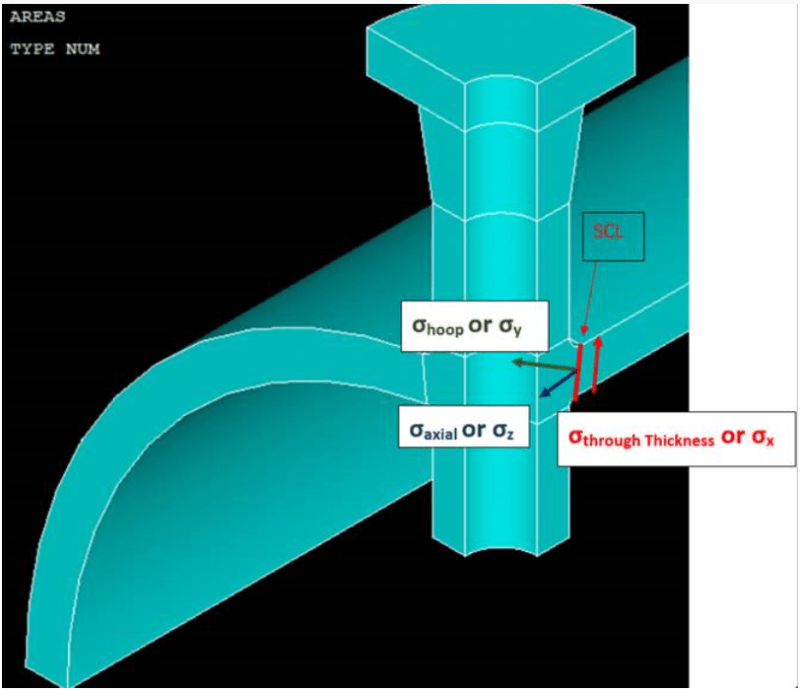
For example, if I define a local cylindrical coordinate system at the center of the vessel with its axis along the vessel’s axis (Pic1.pnj below).

In this system, X becomes the through thickness direction, Y becomes the hoop, and Z becomes the axial direction. Thus, if my Stress Classification Line (SCL) is in the through thickness direction of the vessel (red), are the membrane and bending components of the axial stress (blue) the controlling stresses to which the Code refers?
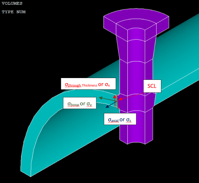
If I change my SCL to that shown in Pic2.pnj (below),

Do I continue to use the linearized stress components in the axial direction of the vessel as my controlling stresses, or would I use the linearized stresses in the hoop direction of the vessel as the controlling stresses.
In the case of Multiaxial Fatigue, would I use the membrane and bending components of shear stress τyz for equation 5.69?
How could I apply the same method to estimate the equivalent stress range at the weld throat? My SCL will be at approximately 45 degree to the axial axis?
Also, does the choice of stress components change according to the loading condition?
Thank you for your time and attention.
TN
I recently started studying Article 5.5.5 “Fatigue Assessment of Welds – Elastic Analysis and Structural Stress”. As I worked out some examples, I found that it is confusing to choose the correct linearized stress component for equation 5.57. According to the Code, “The controlling stress for the fatigue evaluation is the structural stress that is a function of membrane and bending stresses normal to the hypothetical crack plane” (article 5.5.5.1 (a)).?
For example, if I define a local cylindrical coordinate system at the center of the vessel with its axis along the vessel’s axis (Pic1.pnj below).

In this system, X becomes the through thickness direction, Y becomes the hoop, and Z becomes the axial direction. Thus, if my Stress Classification Line (SCL) is in the through thickness direction of the vessel (red), are the membrane and bending components of the axial stress (blue) the controlling stresses to which the Code refers?
If I change my SCL to that shown in Pic2.pnj (below),

Do I continue to use the linearized stress components in the axial direction of the vessel as my controlling stresses, or would I use the linearized stresses in the hoop direction of the vessel as the controlling stresses.
In the case of Multiaxial Fatigue, would I use the membrane and bending components of shear stress τyz for equation 5.69?
How could I apply the same method to estimate the equivalent stress range at the weld throat? My SCL will be at approximately 45 degree to the axial axis?
Also, does the choice of stress components change according to the loading condition?
Thank you for your time and attention.
TN
