JSMachine
Mechanical
- Oct 24, 2011
- 31
I recently got Solidworks on my work PC to learn. I bought a tutorial book - "Solidworks 2010 No Expereience Required" and have been through the entire book. There are still some questions I need answers for though.
My main use for the program will just be to model objects in 3D space. I understand the difference between parts and assembly drawings. So what I have started to do is creat a machine. It has a good bit of parts, but I'm only working with 3 at the moment. One will have to be the base feature, and the other parts will be brought into the assembly drawing.
So, I have the base feature, and two of the same part needed to sit on top of that base feature. The first part is inserted (insert component) and it mates to the base. The second part is basically a copy / another instance of that same part. I go over to the feture manager design tree, select the part and hold control while dragging into the drawing space. Another part is created like the other.
However, when I go to mate this part, it tells me the drawing is overdefined and it will not move.
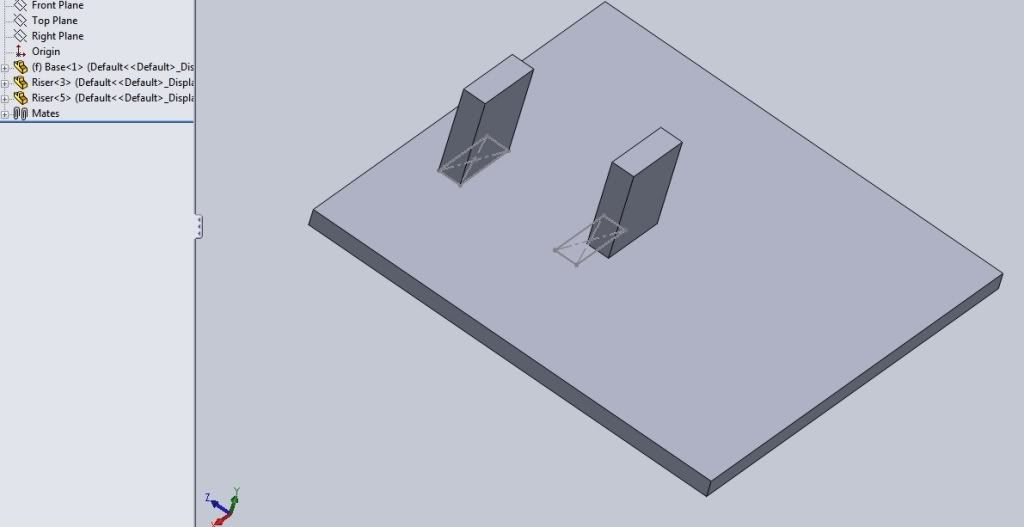
In the illustration I have included, you can see the base, and the first riser block mated to it. the second riser block has been moved into the space, and now I am trying to mate it to the base as well.
I am still not exactly sure how to get those parts positioned correctly on the base, so what I did was go back to the base as a part file, open it up and create a sketch in two places on the top surface of the extrusion that act kind of like footprints. Then, when I open the assembly drawing, I'm trying to mate those parts by using a corner of the riser block to a corner of the sketch on the surface of the base. The point that worked on the first is coincident. it gives me the error on the second attempt with the other riser.

Any suggestions?
My main use for the program will just be to model objects in 3D space. I understand the difference between parts and assembly drawings. So what I have started to do is creat a machine. It has a good bit of parts, but I'm only working with 3 at the moment. One will have to be the base feature, and the other parts will be brought into the assembly drawing.
So, I have the base feature, and two of the same part needed to sit on top of that base feature. The first part is inserted (insert component) and it mates to the base. The second part is basically a copy / another instance of that same part. I go over to the feture manager design tree, select the part and hold control while dragging into the drawing space. Another part is created like the other.
However, when I go to mate this part, it tells me the drawing is overdefined and it will not move.
In the illustration I have included, you can see the base, and the first riser block mated to it. the second riser block has been moved into the space, and now I am trying to mate it to the base as well.
I am still not exactly sure how to get those parts positioned correctly on the base, so what I did was go back to the base as a part file, open it up and create a sketch in two places on the top surface of the extrusion that act kind of like footprints. Then, when I open the assembly drawing, I'm trying to mate those parts by using a corner of the riser block to a corner of the sketch on the surface of the base. The point that worked on the first is coincident. it gives me the error on the second attempt with the other riser.

Any suggestions?
