Eng-Tips is the largest engineering community on the Internet

Intelligent Work Forums for Engineering Professionals

Question about specific design choices of joints.

Status
Not open for further replies.

Burner2k

Aerospace
Jun 13, 2015
193
0
0
IN
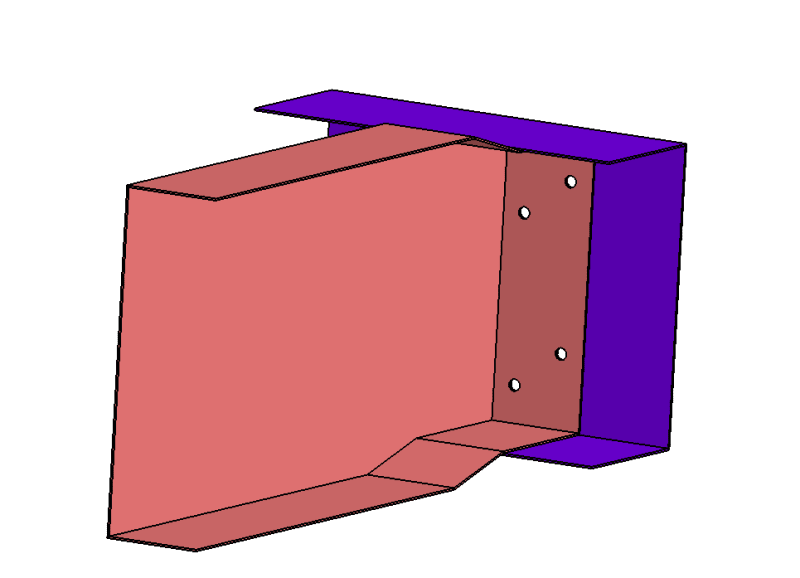
I received a "design" of a rib-spar joint from our design group (for whom the design inputs were received from client). The design contained staggered riveted joints. I was curious to learn about their choice of staggered instead of a usual in-line patterned riveted joint. Our design folks had no idea why such a choice was made and they carried out the design or its modifications just based on client's inputs. I tried to inquire internally but was told that we are in pure delivery mode & learning/research can be undertaken once the delivery is complete...a polite way of saying don't ask unnecessary questions, just do the task at hand.

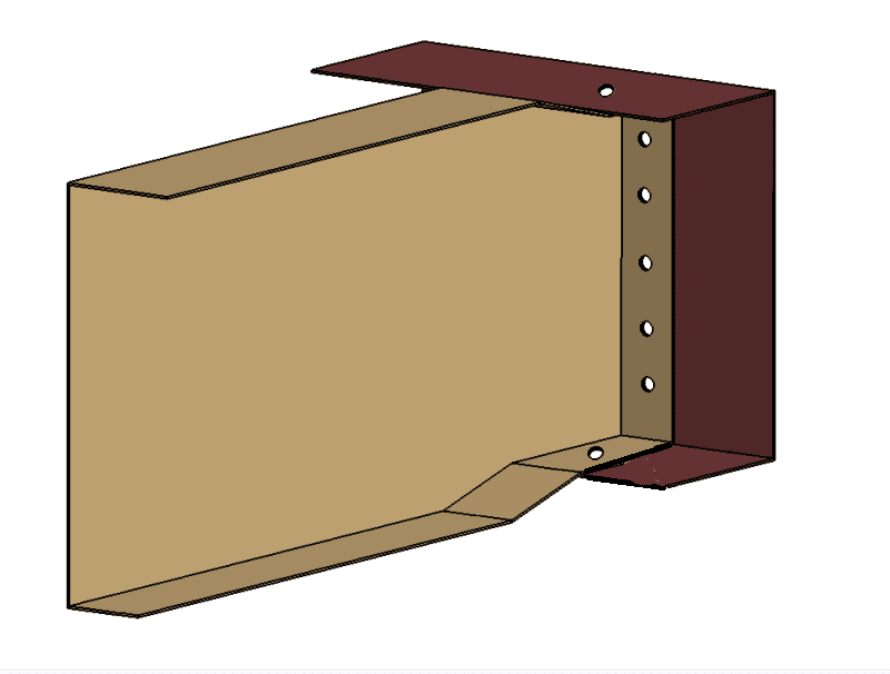
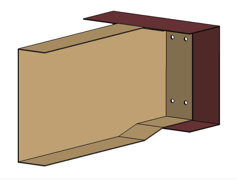
Anyways, I have recreated the design as best as possible. Would the two rivets placed along the depth of the web provide any further additional support? As far as I could make out, there were no spacing issues or clashes, which would make staggered the preferred choice.

03_r5kzeo.png


I also did a design of an in-line patterned riveted joint. Perhaps over the weekend, I will try to a FEM to see if there any benefits in using a staggered vs straight rivets pattern.

01_wmlall.png
 
Replies continue below

Recommended for you

1) I'd place 4 fasteners close to the heel, to work better in shear.

2) nesting machined parts (machined rib inside machined spar) is "tricky". Do you Need to attach to the spar flange ? or is it sufficient for the rib to load the spar in shear ??

3) clients often don't make the best designers ...

another day in paradise, or is paradise one day closer ?
 
RE Rib and Spar...

Are the made from
'thin nested' sheet metal?
'thick-nested' built-up sheet metal?
'100% machined' nested details?

Anything on the forward side of the spar to influence this design? IE: Something to be bolted/fastened that is not shown?

Is 'narrow flange width' an issue for fastener spacing and edge margin?


Regards, Wil Taylor

o Trust - But Verify!
o We believe to be true what we prefer to be true. [Unknown]
o For those who believe, no proof is required; for those who cannot believe, no proof is possible. [variation,Stuart Chase]
o Unfortunately, in science what You 'believe' is irrelevant. ["Orion", Homebuiltairplanes.com forum]
 
My 2 cents:

The wide flange looks odd. This isn't often done, because the rivets closest to the flange do most of the work. Rivets far away don't actually make the joint 2x strong.

If this flange transfers shear from the rib to the spar, and needs 4 rivets to do it, then a FAR more effective flange would have the rivets vertically aligned along the bend. Less flange protrusion, less overlap, less weight, etc. If the flange is extra long to resist buckling, then it would be easier to add an angle to the opposite face of the spar for stiffness and eliminate the rest of the flange all around.

If the rib were loaded until is started to buckle, the flange attached to the spar would initially resist buckling, because the bend makes it stiffer there. Eventually with more load, it begin to deform, too. That deformation would look like a shear buckle, with wrinkles at 45 degrees to the axis of the flange. That 45 degree wrinkle would be either aligned with, or transverse to, the staggered rivet pattern. How the stagger helps, I'm not really sure, and 50% chance of being wrong if I guess.

But if it's going to buckle before it fails, then a few more rivets in a vertical row along the flange would be much more effective than the staggered pattern.

Examples in Flabel's book, and in Bruhn chapter D3.

No one believes the theory except the one who developed it. Everyone believes the experiment except the one who ran it.
STF
 
Folks,
Thanks for the replies firstly.

AFAIK, both the spar & ribs are made of Carbon fiber composites. I have to check again (did not strike me earlier) but I do hope that rivets are not Aluminium...will check with designer on Monday.

Sparweb,
"then a FAR more effective flange would have the rivets vertically aligned along the bend."

Could you clarify this please? Along the bend means?

RB1957, I have asked the question as to if the Ribs are transferring only shear to spar, but yet to receive answers. The popular answer seems to be "this is how we were instructed to do".

WKTaylor,
Is 'narrow flange width' an issue for fastener spacing and edge margin?
The design I've shown may not represent the actual component dimensions although I think it is quite close. I've to check the design again to be doubly sure, which I can do on Monday since I am on leave today.

 
Here are my thoughts on this:

Staggered fasteners typically are used for sealing (think fuel tanks). Another reason would be to reduce footprint of the joint so that your flange can be shorter. However, unless you need to seal or reduce flange width this would not be ideal due to crack growth/fatigue. Your staggered fasteners are aligned with the direction of crack growth in a shear web.

Do you need to connect to the spar flange? The connection really doesn't provide much benefit unless you are transferring moment. This is what Wil is alluding to by asking if you have anything on the other side of the spar. If you have an aileron attach fitting then this would be a proper load path (except that the joggle is not a good design, you need to stabilize this with shims, added stiffeners, etc). See Bruhn D3 as Sparweb mentioned.

Hope this helps.
 
The primary role for ribs is to pick up discrete loads and to distribute them around the wing (wing?)

Ribs want to work in shear, so give them a shear attachment to the rest of the world.

4 fasteners in line close to the web of the rib. Doing this 'cause you don't have (do you ?) a stiffener on the spar, that would make a convenient shear path into the spar. You'll have a double row (with 4 on the other side of the web, yes?) … though is this a fluid boundary ?

Because you don't have a stiffener on the spar (which would naturally fit with the rib being a plane element at the spar interface, yes?) your rib has a flange to pick up the spar web. This flange rather naturally makes you run the skin attach flange up and over the spar flange (to join everything together), even though this complicates the rib (nested interfaces, shimming, …) and doesn't really gain you much. The alternative (having a skin attach flange, a spar web attach flange, and no spar flange attachment) would look "odd".

another day in paradise, or is paradise one day closer ?
 
B2K...

AFAIK, both the spar & ribs are made of Carbon fiber composites.

IF carbon fiber... then are the ribs intended to be adhesive bonded to the spar... and rivets intended to 'locate the parts in-position' and hold them together during bond cure?

Regards, Wil Taylor

o Trust - But Verify!
o We believe to be true what we prefer to be true. [Unknown]
o For those who believe, no proof is required; for those who cannot believe, no proof is possible. [variation,Stuart Chase]
o Unfortunately, in science what You 'believe' is irrelevant. ["Orion", Homebuiltairplanes.com forum]
 
Like this:

01_wmlall_rqrqbk.png


I eyeballed the rivet pitch on the vertical flange, and put in 5 places arbitrarily. It could be 3,4, or 8 depending on the dimensions of the flange and rivets.
I also took the liberty to show you rivets through the spar flanges that may need to be picked up through the rivet flanges. That must be considered, even if you haven't mentioned or asked any questions about it yet.
I also, thirdly, reduced the depth of the flange by half. Unless there is a reason to make the flange wide, it is a waste of material and extra weight.

Now that you've told us the parts are CF, not AL, a whole slew more questions come up. Let's start with the ones already asked.

Bearing in mind that "the customer is always right", of course. [upsidedown]

No one believes the theory except the one who developed it. Everyone believes the experiment except the one who ran it.
STF
 
A cow-orker of mine used to work in aerospace, on the fatigue rigs, testing CF parts. His observation was that using pop rivets as a jigging aid for an adhesive joint was lazy and counterproductive, as you are severing some of the fibres, and providing a compliance mismatch in the joint, hence creating a stress raiser where you've just cut the fibres. Needless to say we didn't go down that path.

Cheers

Greg Locock


New here? Try reading these, they might help FAQ731-376
 
Folks,
Thanks for the replies.

My FEM analysis shows that rivets near the web of the rib do more work compared to the ones farther away. In that sense, the placement pattern illustrated by SparWeb probably is a better design. But if I add a rivet connection from Rib Upper & Lower Flanges to Spar Flanges, won't that create a load path for moment transfer as well? If I am trying to design this joint to transfer only shear to the spar, then I can just retain the rivets along the flanged web of the ribs and delete the upper & lower ones, correct?

I have question about usage of stiffeners but before that I think I will go through Flabel/Bruhn to recall stuff.
 
Burner2K said:
But if I add a rivet connection from Rib Upper & Lower Flanges to Spar Flanges, won't that create a load path for moment transfer as well?

Yes, but consider that those fasteners are probably already there. I this whole structure like a wing, with upper and lower wing skins? Then what fastens the skins to the spar, but either bonds or rivets through skin and spar? I expect it's riveted, since the rib-spar flange is riveted. So where you put this rib will end up aligned with at least one of the fasteners that are already going through the spar cap and skin.

No one believes the theory except the one who developed it. Everyone believes the experiment except the one who ran it.
STF
 
yes, rivets along web are better at transferring load to the spar web.

yes, the cap flanges will transmit (some) moment … presumably this was intended with the design. The "only" to prevent this is to do away with the flanges and have the rib attach (in shear) to a stiffener from the spar web (or a separate Tee fitting on the spar web, and yes, this looks clumsy transferring load into the Tee only for it to be transferred into the spar web, but it is a reasonable option). Once you have rib flanges to the wing skins and the spar web the "only" natural thing to do is to have a rib flange on the spar caps. Yes, this complicates things (build, installation, analysis … but it is your (someone's?) choice. None of these complications are difficult, unless overlooked !

another day in paradise, or is paradise one day closer ?
 
I'm wondering if the customer intends to bond as well as rivet as previously mentioned. If so, I wonder if they've tested the effectiveness of their bond joints. At my previous company we installed a large number of "bathtub" style carbon honeycomb flanged ribs/stringers/etc and the rule of thumb there was that any flange width greater than 2" or so didn't really improve your load transfer capability and we included this limitation in our hand analysis even when the physical bond area was larger for one reason or another.

Being composite, staggering prevents putting multiple breaks in the same fibers in at least one direction, which could be another reason they wanted a stagger pattern.

Regarding previous pop rivet comment, I'd agree. Thought they may be intending to use something more substantial (chicken rivets/belt and suspenders approach).

Cheers,
Nathan
 
Status
Not open for further replies.
Back
Top