Eng-Tips is the largest engineering community on the Internet

Intelligent Work Forums for Engineering Professionals

Question about wheels to use for moving a fixture on an 1/2'' angle rail 9

Status
Not open for further replies.

Cilasefi7

Automotive
Sep 7, 2023
11
0
0
US
Hi guys,
I want to move a fixture that's 100 pounds forward and back (back and forth) on 1/2'' angle rails.
Do you know of any flange wheels or have suggestions on what wheels to use for my application?
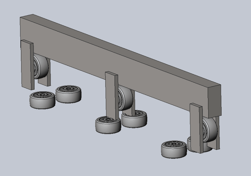
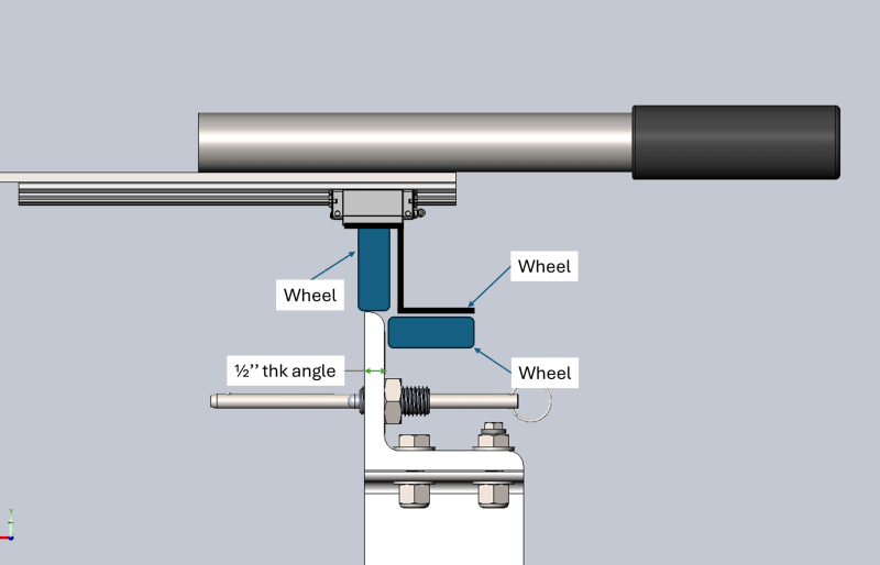
Please see attached sketch of my application, black is a bracket that I plan to mount my wheels to, green are the wheels.

I'm looking for a mechanism to guide the fixture, that's why I put a set of perpendicular wheels, right hand shown only.

I'm considering some type of wheels with flanges or maybe v-groove wheels that can sustain a load of 100-200 lbs.

Any input?

Thank you,
wheels_on_spreader_bar_bq8tch.png
 
Replies continue below

Recommended for you

The arrangement shown stands a good chance of having high contact stresses that will quickly destroy the edge. If you are looking at v-groove wheels, consider using the weld-on track - dualvee
 
Yes, the edge of a rolled-form shape, the 'angle rail', is not a suitable solution, both in terms of the as-manufactured tolerance and finish, and as has been noted, wear-ability. I would think that the already suggested 'DualVee®' system would be exactly what you're looking for. And BTW, the 'V-rails' do not need to be welded-on. They offer several schemes for holding sections of the 'V-rail' so I'm sure that you'll find something which will work for your application.

John R. Baker, P.E. (ret)
Irvine, CA
Siemens PLM:

The secret of life is not finding someone to live with
It's finding someone you can't live without
 
I'd also look at similar designs for reference when determining an approach. The first example I think of is a locomotive rail. They use a flanged wheel so no need for a lateral wheel. This is similar to the DualVee product referenced earlier where the V design provides your lateral alignment to the rail.

<tg>

"If there's something in life you don't like, change it and deal with the consequences." - James Tanton
 
If the load is only 100 pounds or so, as indicated by the OP, even miniature 'Light Rails', the smallest of which is 2 5/8 inch high, would be overkill.

John R. Baker, P.E. (ret)
Irvine, CA
Siemens PLM:

The secret of life is not finding someone to live with
It's finding someone you can't live without
 
What does the other side look like? It seems like there is an overhung load showing, v-groove wheels will not restrain any uplift. It looks like some linear bearings and rail are used. A little more of the story might be helpful.
 
Why not turn the angle section by 90 deg. with the apex upward and use a grooved wheel, the wheel/s could be steel, rubber or other material to suit your requirements, this it will keep it tracking straight and distribute the load more evenly.

It is a capital mistake to theorise before one has data. Insensibly one begins to twist facts to suit theories, instead of theories to suit facts. (Sherlock Holmes - A Scandal in Bohemia.)
 
Do not do it as you have shown. First, the upper wheel will quickly wear out from virtual line contact. Second, the edge of standard angle iron is NOT flat or straight. There are many better options.

The inverted angle with a V-wheel, as suggested above, is a popular option. And it works well...BUT ... the most common mistake made in that arrangement is in the designer's assumption that two inverted angle rails can ever be parallel. They cannot. First, because they aren't exactly straight. And second, even if they were straight, it is impossible to mount two angle rails perfectly parallel. The most common solution to this problem is to use v-wheels on inverted angle on one side of the load, and flat wheels on flat rail on the opposite side. That way the flat wheels will follow the lateral guidance of the v-wheels.
 
I think I'm going to go with the setup mentioned previously of v-wheels on inverted angle on one side of the load, and flat wheels on flat rail on the opposite side.
Do you guys know where I can procure flat wheels with concentric and eccentric bushings, that I can adjust just to make it a tight tolerance?
 
How big? How precise?
Application information? Speed? Duty cycle?

All standard caster companies offer both v-wheel and flat. But eccentric bushings? Not so much.
McMaster has eccentric bushings.
Several good sources come to mind:
Osborn (loadrunners.com)
Bishop Wisecarver (bwc.com)
PBS Linear (pbclinear.com)

Another thought: You don't necessarily need eccentric bushings to level your payload. Often a well-placed shim in the mounting arrangement will do the trick.
 
Do you guys have any design ideas for this setup?

Wheels vertical and horizontal that will run on the track, we're gonna use flat wheels with eccentric bushings on the horizontal wheels for adjustability. I'm having a difficult time dealing with how to fasten the horizontal wheels, any ideas?
wheel_setup_assembly_crj7mh.png
 
If done properly, you may only need the so-called 'horizontal' wheels on one side, if the other side only needs 'vertical' wheels to support the overall mechanism. Optionally, you could use 'horizontal' wheels on both sides, but only one set on each side, either on the inside of the support rails or on the outside.

John R. Baker, P.E. (ret)
Irvine, CA
Siemens PLM:

The secret of life is not finding someone to live with
It's finding someone you can't live without
 
looks extremely complicated and expensive compared to an inverted angle etc as already proposed.

It is a capital mistake to theorise before one has data. Insensibly one begins to twist facts to suit theories, instead of theories to suit facts. (Sherlock Holmes - A Scandal in Bohemia.)
 
Status
Not open for further replies.
Back
Top