Continue to Site

Eng-Tips is the largest engineering community on the Internet

Intelligent Work Forums for Engineering Professionals

  • Congratulations IDS on being selected by the Eng-Tips community for having the most helpful posts in the forums last week. Way to Go!

question on modification of a moineau type pump

Status
Not open for further replies.

geniuskhan

Petroleum
Oct 1, 2015
4
I have read in several studies that a multi-stage progressing cavity pump does not equally share the differential loading. The work done by the first couple of stages is virtually zero, and then the remaining couple increases exponentially. It is almost to the point it is ridiculous to spend the money on the additional stages. Being a subscriber to the "Kaizen theory" about life and making things better, I started to research things a little more.

There are a several solutions regarding this phenomena.
~Solutions such as increasingly less interference between the rotor and stator from the inlet to discharge ends.
~Drilling holes in the rotor complete with check valves to assist in the load equalization.
~Modifying the design so that it becomes a "progressive" cavity, fusto-conical, etc....

I was curious if recirculating a portion of the higher pressure fluid near the final stages of the pump (discharge end) back into the inlet side would serve as a possible option. I'm curious if there would be any positive results by making such a modification.
 
Replies continue below

Recommended for you

I've never heard of making such a modification to a Moyno pump.
Similar modifications are made to centrifugal pumps in order to artificially shift the operating point toward desirable regions, but Moyno pumps are in no way remotely similar to centrifugal pumps, so I would not expect similar results.

I think you'd have to modify the Moyno pump to do what you suggest.
Do not expect any sort of warranty support.


Mike Halloran
Pembroke Pines, FL, USA
 
I cannot imagine why you think any of the modifications you suggest would have any benefit. The only reason these PC pumps have more than one "stage" is to introduce more seals between the input and the output, which allows higher output pressure. There is zero compression in any "stage".
 
The application is actually to use the pump as a motor. Fluid is forced through the PCP to create rotation of the rotor, instead of mechanically driving the rotor to move the media. So the pressure equalization would provide a wider power band and thus more power output.

The Caveman approach to our industry has been more stages = more power...grunt grunt grunt. Sadly the extra stages are merely added dollars with negligible and marginal efficiency for the investment.

Warranty is not of any concern. We get 300 operating hours at best before we repair the stator
 
Interesting. Given I had always thought of the PC type pumps as essentially PD pumps, using it as a generator is quite novel.

I am quite surprised there isn't a more efficient option oput there, but as you don't say what the fluid is (PC pumps are normally used for abrasive fluids with big stones in it), maybe it is worth it.

The philosophy behind these pumps is a little strange so perhaps some more reading up on them would be useful.

In either situation, I find it difficult to understand how bypassing part of the pump / turbine, is doing any good.

Perhaps a diagram would help?

Remember - More details = better answers
Also: If you get a response it's polite to respond to it.
 
That's veering off topic, but like LittleInch I'm curious why a PC pump is the best choice for a hydraulic motor in your application.
 
It appears to me that either the type of fluid travelling through the pump would quickly render your proposed "solutions" inoperative, or you have selected the wrong type of pump to use as your hydraulic motor. Moyno-style pumps are rarely the best selection for clean fluid services- as LittleInch has said, they're typically used for viscous pastes or for slurries. They're not very efficient as they're optimized for survival against the abuse they take from exposure to the fluids they handle, rather than for mechanical efficiency.

I'll leave it to others to see if they can understand what problem you're actually trying to solve with the pump design.
 
If what you are posting is true, then the manufacturers of these pumps would be fools to try to sell the pump with extra useless stages. The competitors would quickly figure it out and sell pumps with less stages. Common sense says that it can't be true because the manufacturers are selling these pumps with more stages.

If you are only getting 300 hours operating time before failure, you need a different pump. These pumps are ridiculously expensive to repair.
 
As Comp said to begin with, these pumps have stages to assist with sealing, they aren't supposed to have equal loading. You could build a single stage, but you can't seal it tight enough to reach operating pressure.
I have seen modified profile rotary screw compressors used as motors, they are very efficient. And they work very similar to PC pumps.

= = = = = = = = = = = = = = = = = = = =
P.E. Metallurgy, Plymouth Tube
 
Thank you everyone for your input. I'm not an engineer so I came to the experts for some assistance, and it is much appreciated.

LittleInch said:
I am quite surprised there isn't a more efficient option oput there, but as you don't say what the fluid is (PC pumps are normally used for abrasive fluids with big stones in it), maybe it is worth it.

the application is in a harsh environment (solids/abrasives/temperature/high torque requirements) and it also restricted diametrically. So the PC pump is the best fit for application. Turbines are used as an alternative, however the RPM output is typically too high and gear reduction systems don't provide the reliability or desired torque output.


LittleInch said:
In either situation, I find it difficult to understand how bypassing part of the pump / turbine, is doing any good.

Perhaps a diagram would help?

The idea was to recirculate the increased pressure back into the inlet side. However I have several concerns.
1. The possibility it would go into self-destruct mode by continually recirculating increased pressure, so the Pressure relief valve may prevent that.
2. Is the lower volume of recirculated fluid (approximately 20%), albeit a higher pressure, substantial enough to increase the overall working pressure of the initial stages of the pump?

Here's a rough sketch...The numbers are merely examples.


sketch_urx55y.png


The thought is to increase the pressure capability of the pump, by improving the work load performed by all the stages, and not just the last few. In theory, this should allow for more differential pressure across the pump and thus shift the torque curve accordingly.

The idea may be totally crazy and not work, that's why I came to the brain trust.

I'm with you BIMR, the extra stages while not a total ruse, it's not worth the added costs. Unfortunately, what I have seen, is that all the vendors know of this phenomena and have spent lots of money studying it. A solution may just not be feasible, and it's just an idiosyncrasy that we have to live with. I'd be happy if I could achieve a 15%-25% improvement. It would be substantial for our application.
 
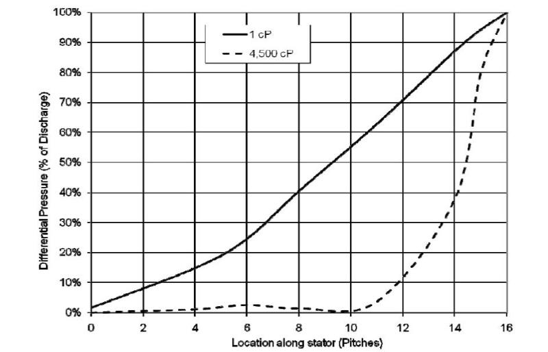
Here's an actual graph of measured loading across each pitch/stage. Some specific applications can run relatively high visc. fluid, however not on the order of 4500 cP.


pcp_graph_pqhwyo.jpg
 
PC motors are now commonly used in directional drilling, which preceeds fracking operations. Rotating the drill pipe to drive the downhole drill head does not allow for steering the direction of drilling. So now motors are used to power the drill bit. These motors must be powerful and fit in the bore of the oil well. The flow of drilling mud powers the motor and carries away the rock cuttings back to the surface.
 
I don't understand the little flowchart. When the pump is in fact a motor, shouldn't inlet pressure be higher than outlet pressure?
Where do you get the fluid for recirculation from? Does your PC motor have an outlet along the casing? Can you point us at some monufactuerers info on the PC motor you are using so we can see the thing?
 
PC pumps have been used for years as "mud motors" in directional drilling tools; nothing novel here.

In general the reason for additional stages is to inhibit the inevitable "slip" of product from one chamber to the adjacent, lower pressured chamber. Each stage added helps to spread the pressure drop and lower what each stage has to handle.

You can also accomplish the same thing by tightening the clearances between rotor and stator, or hardening the softer stator. But then you encounter wear problems by not allowing the softer stator to "absorb" hard particles as the rotor rolls over it. Also there will be much more expensive machining costs to produce the tighter tolerances and reliability reduction.

This whole idea sounds like a very academic exercise that should remain within academia.
 
DubMac has hit the nail on the head. As I suspected, the motive fluid is drilling mud, not a clean fluid, which is why the progressive cavity design is being used as a motor. I don't think that either check valves or closer tolerances are going to do you much good with that fluid in practical terms, if reliability matters. As I said, either the fluid is clean and you've selected the wrong type of motor, or the fluid is an aggressive one and your options for changing the progressive cavity design in meaningful, durable ways will be quite limited by that fact.
 
Inspection of the pump curve present above would predict the same. If you eliminated the first 10 pitches, you would have a 6 stator pump. The curve shows zero flow for a stator pump.

If you left off the last 6 stators, you would also have zero flow, from a 10 stator pump.
 
Status
Not open for further replies.

Part and Inventory Search

Sponsor