Continue to Site

Eng-Tips is the largest engineering community on the Internet

Intelligent Work Forums for Engineering Professionals

  • Congratulations KootK on being selected by the Eng-Tips community for having the most helpful posts in the forums last week. Way to Go!

Question on utilization of diaphragm on steel building

Status
Not open for further replies.

Samuee

Structural
May 11, 2018
20
Hi all,

there are two wind load paths for the steel building I am reviewing.

First,

wind -> external wall -> in-situ slab with shear stud -> steel beam and columns
For this case, diaphragm action is utilized for rc slab connecting to steel beams.

Second,

wind -> external cladding -> steel sub frame -> steel edge beam -> ....

I'm thinking for this case, can we treat that steel edge beam. interior beam and slab as a rigid diaphragm together, so all shear studs evenly share the load? Or the load path should be load transfer from edge beam first then to rc slab through shear studs of edge beams ONLY?

Thanks all
 
Replies continue below

Recommended for you

Show us a simple diagram with the two load paths depicted in your question, and the direction of the wind under consideration. So there is no guess works, and misunderstanding that may lead to incorrect answers/suggestions.
 
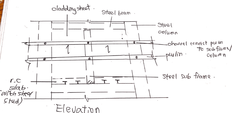
elevation_bgll2z.png


This is case 2

As shown in the elevation, load from cladding transfer to the subframe edge beam, or column directly, while all beam are of in-situ slab with shear stud connected. In this case, can I still assume wind load transfer to the floor slab with diaphragm action?

Thnks
 
Maybe I've missed something, I am still in struggle with your question. If every thing is connected, the lateral force will pass across the building through the concrete slab, that is made of composite with the metal deck by studs, and then the studs connect the composite deck to the beams or to the sub-frame (purlins) that is connected to the beams, to complete the load transfer. So the lateral load will exist in all connections and the connected parts.
 
retired13 thank you for your reply. The rc slab is not connected to the sub frame directly. It only connects to the steel beam below. So if we need rc slab as a diaphragm to complete the load path, wind load has to transfer from cladding -> purlins -> sub frame -> edge beam -> diaphragm (rc slab) through shear studs on edge beams. If this is the case, shear studs on the edge beam will be taking lateral load much higher than those on the interior beams, as load needs to transfer from edge beam through shear studs onto the beam first in order to transfer the loads to diaphragm, and the lateral loads taken by shear studs on the edge beam will be evenly distributed onto those on interior beams.

And you can see purlins are connected to columns too. For wind load transfer through purlins to the columns. Is it weird to think that the loads will transfer to the beam above and below the columns and to the diaphragm, and back all beams and columns again? Or it just directly transfer from the columns and to the beams connected. If this is the case, no diaphragm actions utilized.
 
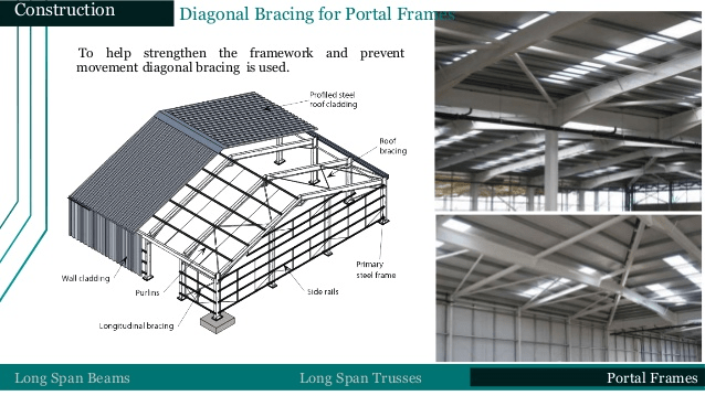
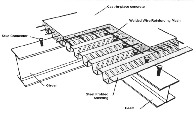
I am fully confused, as your sketch showing elevation view, with the word "cladding", so it is supposedly a view into the wall. But there are studs shown on a beam, and the repeat mentioning of slab, made it feels like framing for a composite slab. Please review the sketches below, and see what is the system you are talking about - metal wall, or composite floor slab. (Also note, the purlin is a roof member supporting the metal deck, is that mean you were thinking about roof diaphragm?)

m_vdhjaz.png


m1_dfmxqs.png
 
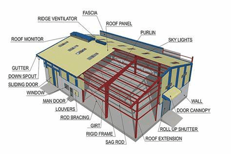
Here is another good illustration of metal building components.

m_zrluca.png
 
Status
Not open for further replies.

Part and Inventory Search

Sponsor