Kunal Gide
Student
Hello,
I am trying to simulate a compression test according to ASTM D695 standard. I created a part which is a cylinder (r=6.35mm and h=25.4mm). The material properties I applied are for PEEK polymer. They are as follows:
Elastic Properties
E= 2600 MPa and v=0.378
Plastic Properties
Plastic hardening= Johnson Cook
A=81 Mpa, B=41 MPa, n=0.23, m=0.76, Tm= 343 C, T0=20 C
Rate-dependent type= Johnson Cook
C=0.0141 epsilon0=1
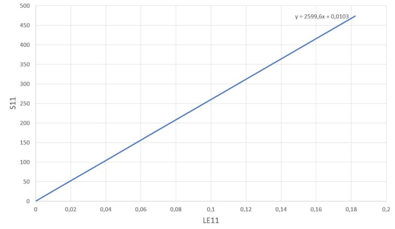
Then I created two RP on the top and bottom surfaces and constrained them using rigid body constraints (Tie). I applied Encastre at the bottom RP and displacement at the top RP as boundary conditions. The step was nlgeom=ON, static general. The mesh size was 0.2mm C3D8R. After I ran the job successfully, I wanted to calculate the elastic modulus by the slope of the stress-strain curve. I selected the whole cylinder and Von Mises and LE Strain (max principle) and took the average value so I got one value per increment for the entire model. Theoretically the resulting modulus should be around 2600 MPa as inputted in material section but I am getting increased modulus around 7000 MPa which is much higher than expected. Can anyone help me figure out the problem in my simulation? Later I want to simulate a similar test with the same material properties for a lattice structure. The material properties were taken from a paper.
Thanks, and regards,
Kunal

