Continue to Site

Eng-Tips is the largest engineering community on the Internet

Intelligent Work Forums for Engineering Professionals

  • Congratulations GregLocock on being selected by the Eng-Tips community for having the most helpful posts in the forums last week. Way to Go!

Questions about DC MG Set

Status
Not open for further replies.

rockman7892

Electrical
Apr 7, 2008
1,156
I'm looking at the attached drawing for a 750V DC MG set for rollers in an aluminum mill and was hoping that some of our gen/motor experts here could help shed some light on a few items for me. These gen and motor units have separate exciter control enclosures and the main 750VDC distribution is fed from generators to motors through a 750V Switchboard lineup which contains breakers and switches shown on one-lines.

1) For both the DC generators and motors there are both separately excited field windings as well as armature windings. From my little experience I'm used to seeing one or the other but not both....either a separately excited field winding or a shunt/series winding but not both. Is there an operational advantage to having both?

2) What are the C&C windings on both gen and motors (purple cloud)? Are these typically located on the units itself or the control/distribution board?

3) What are the resistors and OV relay on the generators for (green cloud)? These appear to be for some sort of overvoltage relaying/detection?

4) the DB resistor in the on the motors (blue cloud) appear to be used for dynamic braking, to slow the motor and prevent it from producing back EMF?

5) What are the resistors (red cloud) used for on the motor circuit. I'm assuming these are used for speed control of the motor with the (3) different contactors being used as means to change resistor value for speed control? What about the resistors on the generators (red cloud) Are these resistors typically on the unit itself or on the control distribution board?

 
 https://files.engineering.com/getfile.aspx?folder=4e3191e3-27c8-4bf7-8f09-009ae38f0b12&file=MG_Set.pdf
Replies continue below

Recommended for you

Typically in an MG type DC drive, the motors have full excitation. The motors will have auxiliary cooling if slow speed running is anticipated.
The speed, speed ramp, overload limits, load compensation, direction and other parameters are controlled by circuits that control the output voltage of the generator by varying the field excitation of the generator.
This was once done by resistor networks and multiple input Amplidynes sometimes directly feeding the generator field and on larger machines feeding the field of a larger exciter generator which in turn fed the generator field.
Now solid state reigns.
On smaller MG sets the excitation of the generator will be static.
On larger MG sets, the static panel will drive the field of a generator type exciter.
The static exciter may have an output of from +200% to -200%.
This is called field forcing.
For fast response,the static exciter may output 200% until it sees that the generator output has reached the set point and then drop back to the set point.
This gives very fast response to control action on large machines such as draglines.

Bill
--------------------
Ohm's law
Not just a good idea;
It's the LAW!
 
C&C Comumtation and ? winding ? AKA interpole?

Bill
--------------------
Ohm's law
Not just a good idea;
It's the LAW!
 
1. This allows the machine to be configured as series, shunt, separately-excited shunt, or compounded in various ways without having to order a different machine type, making it suitable for versatile applications.
2. My best guess is these are a few turns of commutation (interpole) and cumulative compounding windings used to eliminate armature reaction. Use of cumulative compounding windings is a less expensive method of reducing armature reaction than using compensating windings because compensating windings need slots machined into the pole faces.
3. Yes. See triangle note in bottom right.
4. Yes.
5. The resistor in the series field winding circuit would be for speed control; the other resistor is probably starting resistances (is it tapped?) to limit inrush current when starting - I'm guessing S11, S12, and S13 are speed switches that switch in various resistances.

xnuke
"Live and act within the limit of your knowledge and keep expanding it to the limit of your life." Ayn Rand, Atlas Shrugged.
Please see FAQ731-376 for tips on how to make the best use of Eng-Tips.
 
Thanks Waross and xnuke

Most of the items on that drawing (breakers, switches, resistors, etc) are located on a open switchboard type structure which is old and the customer is looking to replace (field exiter units are located in separate location).

I’m curious if just replacing the switchboard with these items if not makes sense to just replace same devices as shown (with more modern versions of devices, relays etc…) or is there more modern system solution for replacing components without re-doing machines and exciter units?
 
In a simplified version of field forcing, an increase fro 20% speed to30% speed may result in the voltage applied to the field circuit going to 200%.
Initially, most of the increased voltage will drop across the resistor due to the induction of the field.
With 200% voltage applied, the field strength will increase much more rapidly than if only the set point voltage (39%) were applied.
As the magnetic field builds up, a greater percentage of the applied voltage is dropped across the field and correspondingly less voltage drops across the resistor.
The voltage across the resistor may be monitored and when the voltage across the field reaches the desired 30%, the applied voltage is cut back to 30%.
Do you have Ampidynes? They are self contained units driven by a motor of about 2 HP. They will multiply a two Watt input signal into a 1500 Watt output signal.
The most common sizes that I encountered were the 1500 Watt units. There were larger, belt driven Amplidynes but I don't recall the ratings.
The amplidyne output could directly control the field and thereby the output of a smaller drive directly. That may be a 30HP or 40 HP drive.
For larger drives, the Amplidyne may excite the field of a DC generator exciter for a further amplification of the control signal.
If a generator's brusshes are short circuited, a very small exciting current will cause a relatively large current to flow in the armature. This sets up a strong magnetic field at right angles to the original field.
A second set of brushes at right angles may be used to draw a higher voltage and current than the original exciting current.
A gain of 750 was common.
Due to the small initial exciting current required, there was room for three or four field windings.
Each of the windings could drive full output.
The windings could be used cumulatively or in opposition. Different functions could use different windings to adjust the output.
Anecdote alert:
An example of an application to illustrate the use and versatility of an Amplidyne controlled drive.
A lumber mill had a very large sash gang saw.
A cant, or timber would be sawed into 2" thick slabs for dimension lumber.
A cant may be 12" wide by 8" thick, or at times cants over 24" wide would be stacked up 24" or 30" high.
The challenge was to utilize the max capacity of the 300HP sash gang motor by controlling the speed of the feed rolls.
A characteristic of a sash gang is a measurement called the overhang. The overhang times the stroke rate determines the maximum feed speed.
A DC drive was used to drive the feed rolls at the maximum allowable speed.
The first winding of an Amplidyne was used to set the speed.
A CT was installed on the supply to the 300 HP motor. The CT output was rectified and sent to the control panel.
The panel had a DC power supply and voltages were developed across resistor voltage dividers.
The output of the CT was compared against a reference voltage that was set to equal the CT output when the motor was at full load.
With a diode to block reverse voltages, the output was fed to a second winding in the Amplidyne to oppose the main winding.
The resistors were adjusted so that the feed ran at full speed until the motor reached full load. Then the feed speed was reduced to hold the motor at full load.
When the gang was running unloaded and a stack of cant's hit the saws at full feed speed, the overload would actually back the cants away from the saw and slowly feed them back to the saw as the saw came back up to speed and the acceleration current dropped.
[/a] Yes, I know, I need an editor.

Bill
--------------------
Ohm's law
Not just a good idea;
It's the LAW!
 
Thanks for the responses.

Waross - From what I can tell there are not Ampidynes used with these motors. The excitation is controlled by a static exciter with the armature circuit used to control speed (through resistors?).

I've attached (2) additional drawings showing other similar motor applications in this facility with different control methods and had a couple additional follow-up questions

1) On the attached "DC Drive 1" drawing the DC motor is fed from a DC drive with the output of that DC drive feeding the armature circuit shown here. The motor is separately excited through a static exciter with a shunt field. The breaker shown on this drawing resides on a 700V open construction switchboard type arrangement with the only components on this structure being this DC breaker along with current and voltage feedback signals. My question here is weather or not there is a need to have this DC breaker on a stand alone structure if the DC drive itself has a high speed output breaker? Seems a but redundant to me but perhaps I'm missing something.

2) On the attached "DC Drive 2" drawing there are two motors that are fed from the same DC drive with the output of the DC drive (terminals at bottom of drawing)feeding the armature circuits for both these motors. The motors are separately excited by a static exciter which feed both shunt fields in series. What is the advantage to having both of these motor armature in series as well as both of the shunt fields in series as opposed to having them individually fed similar to first attachment (cost perhaps)? Similar to Drive 1 the contactors shown on these drawings reside on an open air DC switchboard. Is there a particular reason why contactors would have been used here as opposed to breakers as shown on other drawing? Are the resistors shown still needed with operation from a DC drive?
 
 https://files.engineering.com/getfile.aspx?folder=fa01f9db-668b-487a-8cc3-2e171bce2b98&file=DC_Drive_1.pdf
Not familiar with this type of drawings.
In case 2 I would think that this solution is because the motors will always go with the same speed, even during most fault scenarios.
That can be a good thing depending on the machines function.
Even if a fault occurs in the electrical a mechanical fault that comes of it can make it three four times worse, before you get going again.

/A

“Logic will get you from A to Z; imagination will get you everywhere.“
Albert Einstein
 
There is a lot of proprietary information behind those drawings.
Unless the resistors are heavy cast grid resistors, they are for control circuits.
The basic Motor Generator DC Drive circuit is sometimes called a Ward Leonard Circuit, but the term may not apply to all DC drive circuits.

1. The motor shunt field is continuously excited. This may be from a small generator or a static exciter.
2. The motor armature and the generator armatures are connected in series.
2. The generator shunt field is energized by a variable voltage exciter.
The generator may be excited by a variable rheostat, by an Amplidyne and a much smaller reostat, or by a static exciter.​
Larger machines may be excited by a small DC generator which in turn is excited and controlled by a static exciter or an Amplidyne.
The basic principle is that a DC motor with an excited shunt field may be speed controlled and reversed by applying a variable voltage to the armature.
The voltage and polarity of a DC generator may be controlled by varying the voltage and polarity of the generators shunt field.
Then there are compensation circuits:
Compensation for voltage drops under load.
Torque limiting.
Speed regulation under load.
Speed limiting.
Provisions for compensation in the event of overhauling loads.
Limiting circuits for overhauling loads.
Speed ramping.
The overvoltage relay may be for a stop in the event of overspeed. It may drop the excitation voltage in the event of overspeed or it may do something else.
I have worked with Amplidyne excited generator fields.
Amplidyne excitation of a small DC generator that in turn excited the main generator field.
Static excitation of a small generator which in turn excited the fields of several generators in series with several motors.

Bill
--------------------
Ohm's law
Not just a good idea;
It's the LAW!
 
Why are the generators and motors in series?
That balances the speeds and torques of all the motors.
One excitation system may be used to excite all the generators.
One system that I worked on had the following arrangement:
The excitation of the generators was by a static exciter driving the field of a small generator which in turn excited all of the generators in a set.
Four 1300 HP motors in series with four 1300 HP generators.
Four 1050 HP motors in series with four 1050 HP generators.
The generators could be series connected with jumpers.
The motors could be series connected with jumpers.
Only two conductors needed to be run from the generators to the motors.
The savings in copper were substantial.
Further to the comments on compensation circuits:
The max speed of the lower drive of the main hoist was limited to less than the maximum hoisting speed.
If a full bucket was lower to fast it would go into runaway.


Bill
--------------------
Ohm's law
Not just a good idea;
It's the LAW!
 
I am sorry that I can't give you more specific information on your machine. I am not familiar with the operating parameters of aluminum rolling and while the drawings will be helpful for hands on trouble shooting
Reverse engineering from a distance without knowing the resistor values nor the operating parameters is almot impossible.
The last time that I worked on one of these systems was over 40 years ago.
image_v5nm3m.png

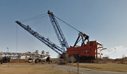
The machine has been decommissioned and placed on display for over 10 years.

Bill
--------------------
Ohm's law
Not just a good idea;
It's the LAW!
 
So far so good, from the folks who've answered to date.
1) C+C stands for "commutating" (aka interpole) and "compensating" (aka pole face) windings. Both are used to adjust the machine's magnetic field to optimize commutation, which is the critical phenomena in a DC machine - motor OR generator. Both have current flowing through the windings that is directly proportional to armature current, so that as the armature draws more current, the magnetic field strength of these windings also increases, keeping everything balanced on the proverbial tightrope.
2) The main field winding for this size machine is most commonly referred to as a "straight shunt" winding. The "series" windings that are sometimes used are essentially "trimming" the field strength by using a portion of armature current to either be cumulative (e.g. add to the main field strength) or differential (subtracting from the strength). Usually the series field is a much larger wire section than the main field and is wound over top of the main winding.
3) Good engineering practice is to have separate main field excitation for each machine in a lineup, as well as separate armature supplies. This is to help accommodate eccentricities in manufacture resulting from hand-forming components such as windings to different properties of materials. Think of it as " infinite adjustment". If either the armature or (main) field windings are connected to the same supply, the ability to adjust one machine without affecting the other becomes much less.
4) That being said - it is fairly common for DC-DC MG sets such as this to have the armatures connected in series. In essence, the "source" for the DC motor armature current is the DC generator armature. The motor's armature voltage control is accomplished by varying the field strength on the generator; the motor's field strength is then adjusted (by a different source than that used for the generator) to most efficiently perform the required task.
5) The OV relay and resistor combination is used to prevent excess energy from the generator being passed along to the motor windings and possibly damaging it. It's just as it sounds - the relay "bleeds off" current to the resistor bank, should there be a problem.
6) The DB (dynamic braking) resistor assembly is used for a similar purpose, except for the motor. It "bleeds off" excessive energy from the motor field to allow it to safely decelerate in the event of a fault. Modern power electronics controls would use a "regenerative" quadrant to accomplish the same thing.
7) Those last few resistors in the circuit (your "red cloud" devices) are "trimming" resistors. They provide some fine tuning to main field strength to permit optimize commutation across multiple load/speed points. These may be a "set and forget" style, in which case they're set by the factory and not meant to be touched by the user. Others have multiple contacts (think variable resistor or rheostat) that can be externally switched through a control scheme of appropriate contactors. Where they are physically located depends on the manufacturer of the rotating equipment and the overall control scheme: most often, since the circuit is never intended for adjustment by the user the resistors are located within the machine enclosure (typically on the motor frame, somewhere below the motor foot plane - perhaps at the commutator end, and perhaps somewhere else). Note that for this purpose, the "enclosure" can sometimes also include the pit area below the motor foot plane.

Converting energy to motion
for more than half a century
 
GR8blu

Thanks for the additional info.

Based on your response I'm assuming that the C&C winding would obviously be located in the motor itself?

Also based on your responses I'm guessing that the trimming resistors are located at the motor frame itself as you indicated is sometimes is the case. The only resistors I saw in the Switchboard itself are in the attached photos which I think are either DB or resistors on gen OVB circuit so I don't know where else these resistors could be. I will note however that the (3) contactors associated with the lower resistor are located on the Switchboard. Does it seem practical that these trim resistors would at the motor? (I intend to look when returning to site)

As mentioned above the only resistors that I found at the Switchboard were the (2) in the attached photo). These appear to be identical in nature and from what I can tell are wired in series which leads me to believe that these are the R1B and R2B associated with gen OVB circuit? Based on the size of these resistors would you expect them to be the .13ohm DB resistors or the 400ohm resistors in series on the gen OBV circuit?

Thanks for the help
 
 https://files.engineering.com/getfile.aspx?folder=d93613d2-33e5-45a9-9169-8f7a05bfff6d&file=IMG_3587.JPG
Grid resistors tend to have very low ohmic values. 0.12 ohm is reasonable for a grid resistor.
I think a 400 ohm resistor is more likely to be wire wound element on a ceramic spool than a grid resistor.
 
Can anyone explain why the DC Drive application would need a separate breaker stand located out in the field as opposed to just having the DC breaker on the output of the drive to open armature circuit?

I posted the specific one-line again below. The only think I see the additional breaker panel in the field providing is an additional means of disconnect as well as armature circuit current feedback, but both of these are available at the drive so cant seem to determine the function here, other than "That's what we've always had"?
 
 https://files.engineering.com/getfile.aspx?folder=e0dc32ad-6ccc-48f8-bd32-5aa49c989bde&file=DC_Drive_1.pdf
rockman7892: Your first instinct - that the "way we've always done it" is to have what is effectively an emergency stop capability close to the DC drive motor is correct. But first you need to understand the logic behind that approach. DC machines work great when the armature (rotor) voltage and the stator (main field) current work together in concert. The loss of of one or the other causes things to happen that are inadvisable from a either a personnel or equipment perspective.

If the armature voltage stays high and the main field current is lost, the restraining effect of the main field magnetic circuit is lost, which in turn leads to a sudden rapid rise in rotational speed. By sudden, I mean it happens in fractions of a second, and the actual overspeed value is only limited by how long the machine can hold mechanically itself together. In contrast, the loss of armature voltage while still maintaining main field current results in an abrupt loss of torque - which may result in a dropped load or other failure of the process. Either failure mode can cause injury to nearby personnel and/or equipment, including but not limited to the machine itself. Since one possible power source is the drive, is there a failure mode (internal to the drive) that would allow power to flow to the DC machine? I suspect there is - which would mean having a backup plan such as an external breaker near the process would be a good idea.

Having the breaker handy to be SURE both armature and field are de-energized makes things much easier on the folks doing maintenance work on the machine, as well as supply some peace of mind for limiting consequential damage in case of a catastrophic event. The other reason for having a dedicated breaker close to a specific machine setup is that the source may have other powered branches - not just the one you're working on. Think of it being like a circuit breaker at home: you can selectively cut power to the dishwasher without disconnecting everything else in the house.

Converting energy to motion for more than half a century
 
Gr8blu

Thanks for the info, that is helpful. After reading your comments and looking at the system topology again i realize that one of the reasons why thy may have the additional breaker and means of disconnect in the field is to be able to verify both the positive and negative legs of the circuit.

Right now the DC drive only has a breaker on the drive at the negative output of the drive with the positive output from the drive going directly from the drive to the motor with no physical means of disconnect at the drive. Thus the panel in the field with the breaker is on the positive leg of the circuit before it reaches the motor to allow isolation of both the positive and negative legs of the circuit prior to the motor.

I'm assuming that from an electrical safety standpoint you need to verify that both positive and negative legs are interrupted (ideally with physical disconnect). I'm not entirely familiar with these types of DC circuits but if the circuit is energized from the source and the positive leg is broken (via breaker etc..) will there still be a potential on the negative leg of the circuit in reference to ground (IE a hazardous voltage)?

In your response you mention a convenient means to disconnect the field circuit as well. In this particular application the armature circuit from the DC drive goes through the additional field disconnect means however the field circuit is a completely separate circuit that goes directly from the static exciter out to the field windings of the motor. Is there perhaps a gap related to the current arrangement based on your response above?
 
One follow-up question to the above...

With a DC circuit for this type of application do you typically need breakers on both positive and negative poles to detect potential ground fault or do you only need on one pole with a disconnecting means on other for isolation purposes?

Is that a matter of how/where system is grounded? For instance on most DC control circuits for breakers, etc... I typically see both the positive and negative side fused.
 
rockman7892: To answer your 29 Sep post - I was kind of lumping apples and oranges into the same fruit basket when I mentioned being able to shut down both the armature and field power from somewhere local to the machine. I did not mean to imply that both would be fed from the same breaker - rather, that having a breaker for each circuit close to hand gives the maintenance group more peace of mind when doing their thing.

From your 4 Oct post - yes, both the positive and negative sides should be interrupted as a "norm", although some grounding arrangements could maybe get away with only breaking one side or the other. Remember that a DC motor could readily become a DC generator - it all depends on the direction of power flow. So if we only "broke" the connection on one leg (positive or negative) we could have a situation where the drive is cut off from providing power to the motor - but the motor can still physically rotate, in which case it becomes a generator and feeds power back up the still-connected line. Would this give rise to some touch-potential issues where the shaft (or something else) was at elevated voltage relative to the ground plane? Quite possibly.

In terms of whether you should be breaking both polarities, think about a 3-phase circuit breaker. Would you only open one of the phases? Two? Or all three? The reason they don't normally include a "ground" contact is that the downstream (or, theoretically, upstream) circuit being protected may not have an accessible ground connection (think delta winding in transformer or motor).

Converting energy to motion for more than half a century
 
Status
Not open for further replies.

Part and Inventory Search

Sponsor