Eng-Tips is the largest engineering community on the Internet

Intelligent Work Forums for Engineering Professionals

  • Congratulations waross on being selected by the Eng-Tips community for having the most helpful posts in the forums last week. Way to Go!

Questions about Story Shear and Overturning Moment Forces Plot in ETABS

Status
Not open for further replies.

Eng-Kh

Civil/Environmental
May 16, 2017
8
KH
Dear engineers,

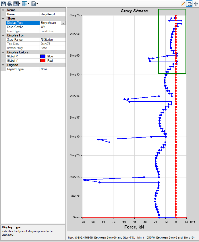
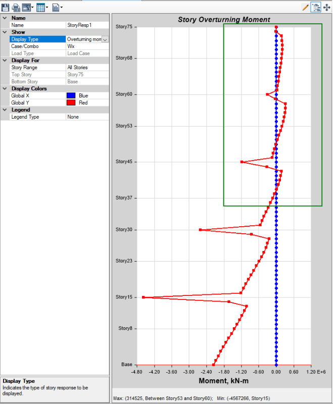
I modeled a building in ETABS, and under wind loading, then I got the result of story response forces like this.

The semi-rigid is assigned, and the slab are flat slab.

I wonder why the overturning moment and story shear force reverse the value from negative to positive value at certain story as I highlighted.

Is there any problem with this? what caused that problem?

Thank you in advances for your ideas.
BD_f4iv7w.png
Story_Shear_hfw4ge.png
OT_Moment_cp1okq.png
 
Replies continue below

Recommended for you

Impossible for me to know for sure. But, I suspect, your floor levels are sloped in some way, right? Perhaps the diaphragms are taking some of the lateral shear locally in the area.

It's kind of like a shear diagram at a point load. Right at the point load the shear value is numerically difficult to represents. But, if you move 0.1 inches to the left or right of the point load, then the shear diagram makes perfect sense. Just a guess, as I'm still learning ETABs and cannot consider myself an expert.
 
Had a similar problem a little while ago with a complex model. I contacted CSI about it and found the solution to be ensuring that all elements are broken/meshed at each floor.

Do you have any braces, walls or columns that span over multiple floors? This can skew these plots.

 
Dear JoshPlum,
The floor level are not slopped. it is flat. Yes, the diaphragm takes in-plane shear as well. I use Auto-Wind load in ETABS. Would you mind explain more about move 0.1 inch left or right point load? I don't really get it.
Thank you very much for your response.
 
Dear Trenno,

I have long column over that separate at 15 story height without divided at each story. I don't divide because I study Big mega column, and I assume that the flat slab is not sufficient enough to separate the columns effective length at each story.

Thank you very much for your response.
 
So, when you have a point load P at the mid span of a beam, you have a shear of P/2 on the left side of the beam and a shear force of -P/2 on the right side of the beam. Correct?

What is the shear at exactly the mid point? There isn't a single correct answer, as the shear diagram has a discontinuity at that point.

I mention this because depending on how a program determines shear force at a given location (even for story shear) you can run into similar issues. I was assuming that the diaphragm at those levels was taking (or re-distributing) some of the shear leading to the odd looking diagram, but that when you're further away from the diaphragm the diagram looks normal again.
 
Eng-Kh,

That's the reason. Break the column at each floor and the plot will seem reasonable again.

Or do a save-as and make the change if you don't want to mess with the original model.

 
It looks as though you have virtual outriggers at the same levels as the spikes in story shear forces and moments, could that be the cause of these spikes?
 
Status
Not open for further replies.

Part and Inventory Search

Sponsor

Back
Top