Nick6781
Structural
- May 15, 2024
- 30
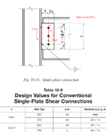
Per Table 7-1, a ¾” diameter A325 bolt has a shear capacity of φ * rₙ = 17.9 k when the threads are included in the shear plane. Page 10-89 indicates that bolt shear must be checked with the assumed eccentricity shown in Table 10-9, where e is determined to be a/2 for a 2-bolt connection. Page 10-91 states that the tabular values (in Table 10-10) are based on a = 3”. Therefore, for a 2-bolt connection, e = 3”/2 = 1.5”. Table 10-10a lists the capacity of a 2-bolt connection as φ * Rₙ = 25.1 k when the threads are included in the shear plane.
For eccentrically loaded bolt groups, page 7-19 indicates that the C value given in Table 7-6 can be linearly interpolated. Thus, C = (1.63 + 1.18) / 2 = 1.405. Therefore, φ * Rₙ = C * (φ * rₙ) = 1.405 * 17.9 = 25.1 k.
We know that the bolt shear capacity governs the connection design, and the tables in the manual are consistent across chapters.
Based on the above, I have the following questions:
- The total moment due to the eccentricity a is P * a. If half of it is transferred to the bolt group, does the other half go to the weld connection based on equilibrium?

- When the number of bolts is between 6 and 12, the considered eccentricity for the bolt group design is taken as a instead of a/2 for standard holes. What is the rationale behind this? What is the moment on the weld group in this case?
- Is the assumed eccentricity in the table based on test results or engineering mechanics principles?
- Table 10-12 lists the bolt and angle strength for a bolted-welded single angle connection. For a 2-bolt connection, the capacity is 35 k. How is this value derived? Why does it appear that eccentricity is not considered in this case?
