Continue to Site

Eng-Tips is the largest engineering community on the Internet

Intelligent Work Forums for Engineering Professionals

  • Congratulations KootK on being selected by the Eng-Tips community for having the most helpful posts in the forums last week. Way to Go!

Queston on Basic Mechanics of Trusses

Status
Not open for further replies.

NAFTALI-HAKOHEN

Civil/Environmental
Apr 8, 2021
26
am struggling to understand something,

in a simple truss with cross bracing like this:
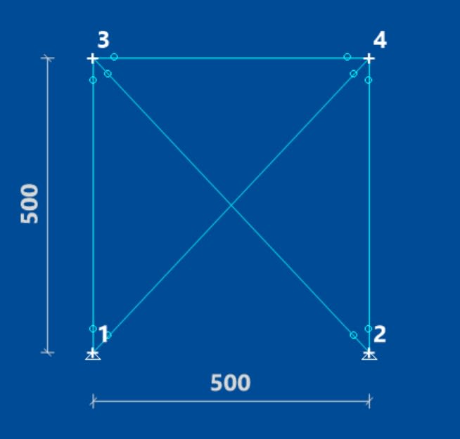
Screenshot_2021-08-12_233348_unzqis.jpg


why are the axial force compressions in the diagonal braces not equal when the structure is loaded with a unit horizontal force:
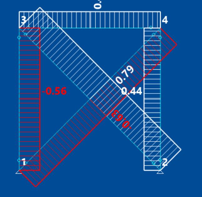
Screenshot_2021-08-12_233526_y9fjy5.jpg


the horizontal reactions at supports are not equal as i would expect....

is it to do with the FE taking the unequal displacements ie unsymetrical displacement of upper beam?

thanks
 
Replies continue below

Recommended for you

It looks like you are applying your load at node 3. If you do that, member 3_4 will increase in length some because it is in tension. That means node 4 will move a little less than node 3 so member 1_4 will have less force than member 2_3.

The forces in your diagonals should match if you apply half the load at node 3 and half at node 4, but think about how the load is actually being applied to your frame to see if that makes sense to do.

Structural Engineering Software: Structural Engineering Videos:
 
If the member sizes are symmetric and the load is placed midway between Node 3 and 4, then the horizontal reactions should be the same as PPE notes above. These are often analysed by pin connecting Node 2 and putting Node 1 on a roller support and treating the compression diagonal as a 0 member (don't have to be). The compression diagonal is used for resisting the load from the opposite direction (it becomes the tension member). This allows you to analyse it as a determinate structure.

Rather than think climate change and the corona virus as science, think of it as the wrath of God. Feel any better?

-Dik
 
"why are the axial force compressions in the diagonal braces not equal when the structure is loaded with a unit horizontal force" ... cause one diagonal is in tension and the other compression. The two diagonals have different load magnitudes because of the fidelity (or infidelity) of the FEM. A hand calc would have the uprights equally loaded (in magnitude, opposite direction), which would make the diagonals equally loaded. The FEA is no doubt finding a difference in the deflection of node 3 and 4. The element 3-4 is going to strain (due to 1/2 the applied load, ok about 1/2).

It could be that your material has different E in tension and compression ?

another day in paradise, or is paradise one day closer ?
 
As others have noted it is statically indeterminate and the first diagonal is a slightly stiffer load path (compared to the second which also has to strain the horizontal member). Thus slightly more load goes via the first diagonal.
 
why are the axial force compressions in the diagonal braces not equal when the structure is loaded with a unit horizontal force

A horizontal loading is, by definition, asymmetrical, so you shouldn't expect equal loading. One diagonal is in compression and the other is in tension.

The structure is only equally loaded if the load is vertical and symmetrically placed around the axis of symmetry. Any other vertical loading would likewise result in asymnmetries

TTFN (ta ta for now)
I can do absolutely anything. I'm an expert! faq731-376 forum1529 Entire Forum list
 
IRStuff, it’s not because of assymetry, it’s because the horizontal member has to strain to load the second diagonal.

If the horizontal member was infinitely stiff the diagonal forces would be equal.
 
are you applying a load of 1 to the left at node 3 ? If you apply the load at 4 (to the left) you should get the opposite distribution. Now the diagonal from 3 is carrying 56% of the load to node 2 (and the RH vertical 44%).

ok, we understand why this isn't the hand calc 50/50 distribution ... the strain of the upper member. Just to explore this a little more ...

1) try fixing the members at nodes 3 and 4 (more redundancy) ... I expect this'll have a very minor effect on the vertical member loads

2) try joining the diagonals (where they cross) with a pinned joint or a fixed joint.

another day in paradise, or is paradise one day closer ?
 

Hi
thanks all. v insightful

tomh could you expand why the second diagonal is less stiff because its carrying the strain of horizontal member,

not sure i understand that fully,

if horizontal is infinitely stiff how does this change load distribution?

thanks
 
The second diagonal *plus* the horizontal is less stiff than the first diagonal alone. The first diagonal is a stiffer load path (it doesn’t have the horizontal spring as part of its load path), so it carries more of the load.

If horizontal is infinitely stiff then the braces move together, and see the same load.

Conversely if the horizontal spring was very very soft then the second diagonal would see very little load.

Try adjusting horizontal member stiffness and see what you get.


Always do that... a while back, a PEMB that had rod bracing actually made a 'slapping' sound from the x-bracing hitting against each other. A 'U' clamp fixed it.

Rather than think climate change and the corona virus as science, think of it as the wrath of God. Feel any better?

-Dik
 
By applying all the load to one corner, you have two load paths through the structure:

1) Load enters node 3, compresses member 2-3, and is resisted at the boundary condition for node 2.
2) Load enters node 3, compresses member 3-4, stretches member 1-4, and is resisted at the boundary condition for node 1.

Think of each member as an axial spring. Since we're assuming elastic response with identical sections (L/AE is equal in tension and compression), compression in 2-3 and tension in 1-4 produce an identical but opposite axial deflection in the respective members. The difference is that in load path 2, you introduce another spring between the load and the boundary condition. Springs in series are added like this: 1/(1/k[sub]1[/sub]+1/k[sub]2[/sub]). So the total spring stiffness for load path 1 is higher than load 2. Load follows resistance (stiffness), so you end up with a proportionally higher load in load path 1.

If the horizontal member is infinitely stiff, then you would remove the additional spring from that load path and 1 and 2 would have essentially equal stiffness and equal load. That's not to say an FEM program will tell you that they have exactly the same loading, but it should be very close.

Note that the spring combination equation above is a generalization.
 
even with an infinitely stiff 3-4 member, the FEM will probably detect a difference in Et and Ec so the load won't share 50/50.

You could make it 50/50 by applying 1/2 the load at 3 and 1/2 at 4 ... but that's "cheating".

if you apply the load at the mid-point of 3-4 ?

another day in paradise, or is paradise one day closer ?
 
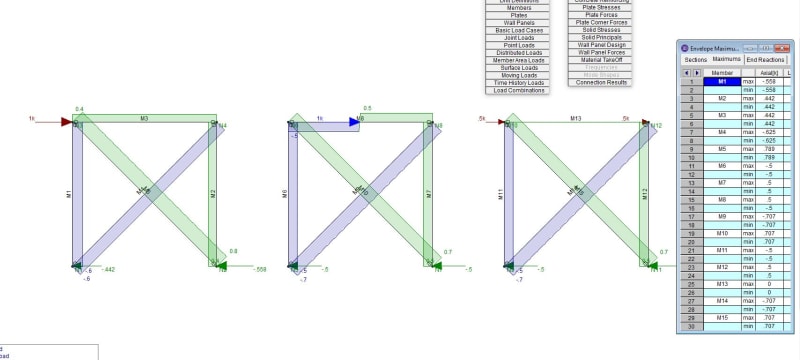
Here it is modeled in RISA with "rigid" members. Hopefully the image is legible.

FEM_with_Rigid_Members_wv3gbl.jpg
 
well I could just read it with it zoomed 500% !

but scenario 2 (loading at the mid-point) and 3 (rigid 3-4) have the hand calc 50/50 distribution.

another day in paradise, or is paradise one day closer ?
 
dik said:
If the member sizes are symmetric and the load is placed midway between Node 3 and 4, then the horizontal reactions should be the same as PPE notes above. These are often analysed by pin connecting Node 2 and putting Node 1 on a roller support and treating the compression diagonal as a 0 member (don't have to be). The compression diagonal is used for resisting the load from the opposite direction (it becomes the tension member). This allows you to analyse it as a determinate structure.

I interpret dik's comment above to mean that one of the lower nodes is considered to be a roller for design purposes, but would likely both act as hinged supports. If the length of diagonal is too long to act in compression, it is reasonable and conservative to assume the tension diagonal takes the whole load.

In actual practice, even if the compression diagonal buckles, it still carries its buckling load. Bolting the two diagonals together where they cross prevents "slapping" and may reduce the buckling length of the compression member, although I seem to remember a thread on this forum where that was discounted.

BA
 
I've heard the 'slapping/rattling'... not urban legend. Often use the diagonal in tension only for simplicity. As far as reducing the buckling length, the Alcan's aluminum design handbook uses 0.45 as the effective K value.

Rather than think climate change and the corona virus as science, think of it as the wrath of God. Feel any better?

-Dik
 
There's another thread going right now on the bolting diagonals together K-factor debate; or at least it's made an appearance. thread172-486213

I'll count on the tension diagonal to brace the compression if - and only if - I can run the appendix 6 stiffness check on it and the brace force calculation causing bending while tension is applied. In assemblies that use bracing members narrow enough to run past one another, I usually find it doesn't work.
 
Status
Not open for further replies.

Part and Inventory Search

Sponsor