Eng-Tips is the largest engineering community on the Internet

Intelligent Work Forums for Engineering Professionals

"Free air" ampacities in the 2020 NEC are now not valid for wire internal to a panel? 1

Status
Not open for further replies.

bdn2004

Electrical
Jan 27, 2007
792
0
0
US
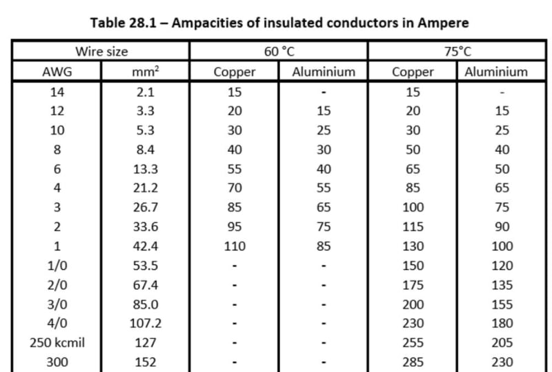
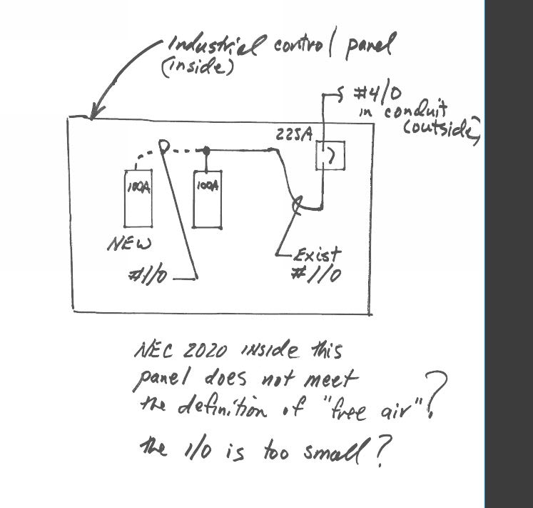
We've an existing industrial control panel that has 225 Amp main breaker in it. It feeds stuff internally in the panel with #1/0 wire. We've added some stuff in this panel. Per the NEC the ampacity for a #1/0 single conductor wire is 230A in Free Air in the 310 Tables but only 150A in a conduit. I'm assuming the original designer of this panel used that Free Air table in the NEC.

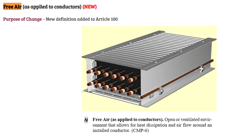
The Contractor is saying the 2020 NEC added a new definition for "free air" and that this wire is not free air by the new definition. So it's all hosed and we need to change out all of the wire.

Any thoughts ?

Free_Air_panel_pa6044.jpg
 
Replies continue below

Recommended for you

I have always understood free air to mean free air circulation such as around overhead lines.
I have never considered using the free air rating inside a panel.
The one time I saw it done I challenged it and it was changed voluntarily.
How was the panel originally acceptable?
Does this panel feed motor loads?
If so then the cable ampacity is determined by the motor overload protection rather than the feeder breaker size.
In such a case, daisy chaining as you show may overload the existing cable.
If so,
Bill
--------------------
Ohm's law
Not just a good idea;
It's the LAW!
 
It’s actually a heat trace power and control panel - located outside, and it doesn’t kick on until the temperature is less than 50degF. That could have been the reasoning on the smaller wiring too, but that doesn’t get it to 225A.

Even modifying it the wire will not be overloaded. The load is well below 225A.

Per the Code tables ... the ampacity lies somewhere between 150 and 230 amps depending on where it is. And then there is the Neher-McGrath method that I’ve never attempted.

The contractor wants to change it all out to #4/0, 230A if it were installed in a conduit. Seems kind of absurd to me on a panel that’s operated successfully for years.

 
Is the interior of the panel governed by the NEC? Or is it a UL 508 panel. I am not fluent in UL508 to know if the ampacity limits are different
 
It was probably done assuming the free air current rating. It's not right.

UL508A allows about 150A with 1/0. So, I assume that panel has no listing mark?
 
No it doesn't have a UL508A listing...And it's entirely possible the panel was originally designed wrong. Do you have the chart? I've worked with panel shops everywhere...I don't think they are scouring UL508A for compliance.

From an internet search the NEC was changed to clarify that cable bus is in open air. Seems kind of hard to believe this qualifies for open air ... but a huge panel with individual conductors does not. Oh well.

Open_air_vzcklt.png
 
Here's a chart I found online....UL508A Table 28.1. Yep #1/0 is 150A. As most panels are not designed to UL508A and you have to be a certified UL508A - does this govern this situation?

UL508A_Table_28.1_kwgjfd.jpg
 
LionelHutz,

Yes it certainly looks like it matches the NEC table for three wires in a conduit.

We are changing it out to 4/0 or (2) 1/0. It's no sweat off of us to make it right. I thought it looked wrong at first glance too...but thinking about it I thought perhaps the free air thing was their reasoning. It could save a little $$ - but not much, and you always get people questioning. To me it's not worth a fight so since we are modifying it anyway put it in a standard way that everyone can agree to.

Hey...you're the one that said it wasn't right - and I agree with you. See what I mean?
 
Status
Not open for further replies.
Back
Top